I will be happy not to worry about that ringing. I just cut a roundover out of 4.5" PVC pipe but was running into difficulties attaching it. Interesting though to see if it affects the ringing.
I first EQed the mid and CD responses flat and to smooth symmetrical slopes and then applied LR4 textbook filters. I know I should EQ the measurements to a target slope. I'm sort of / kind of doing that by eye because I don't have a good way to create a reference waveform.
I wonder if, being they become a point source, if it wouldn't be better to use the at horn mouth measurement instead of the 1m measurements for the XO. Despite the absorbers I had in place the two measurements are different, so there is apparently more of the room present in the 1m measurement.
For this mid driver, the band pass already creates a crossover. Putting one on top of that (LR4) will get you more than you'd want. If a first order "would be" all that is needed to put the acoustic output in the right shape, that really should be all that is needed (except for some notches here and there).
I have used Rephase to get an idea of what a LR4 should look like. It can generate an impulse that can be imported into REW (Import Impulse Response) and could provide a target for the acoustic measurement. I assume you didn't boost the mids back to flat before applying said LR4 filter?
When you have an example filter like Rephase can produce (X-Sim could also do it I suppose) you can use REW's EQ settings to figure out the needed notches and filters to comply to that shape.
I have looked at RePhase to see if it can produce non linear phase crossovers and it can. I could also do that with my JRiver by sending a pure Dirac pulse trough a LR4 filter in it's DSP settings and sent the output to disk to get a wave file. Lot's of ways to be able to see the theoretical shapes. Too easy actually to revert to eyeballing.
Here's a LR4 within RePhase at 900 Hz (not sure where you want it)

Here's the same picture after I save it to an impulse and load it into REW:

While this is only a theoretical example, our acoustic output should be close to that for us to call it a LR4 crossover.
With this loaded into REW, you would have a target to work with. You can determine needed cuts to get the band pass close.
That is, if we are shooting for named crossover slopes. We've seen it is possible to get closer to transient behaviour with the Harsh type XO. But I remember you wanted something more steep on the tweeter.
I have used Rephase to get an idea of what a LR4 should look like. It can generate an impulse that can be imported into REW (Import Impulse Response) and could provide a target for the acoustic measurement. I assume you didn't boost the mids back to flat before applying said LR4 filter?
When you have an example filter like Rephase can produce (X-Sim could also do it I suppose) you can use REW's EQ settings to figure out the needed notches and filters to comply to that shape.
I have looked at RePhase to see if it can produce non linear phase crossovers and it can. I could also do that with my JRiver by sending a pure Dirac pulse trough a LR4 filter in it's DSP settings and sent the output to disk to get a wave file. Lot's of ways to be able to see the theoretical shapes. Too easy actually to revert to eyeballing.
Here's a LR4 within RePhase at 900 Hz (not sure where you want it)
Here's the same picture after I save it to an impulse and load it into REW:
While this is only a theoretical example, our acoustic output should be close to that for us to call it a LR4 crossover.
With this loaded into REW, you would have a target to work with. You can determine needed cuts to get the band pass close.
That is, if we are shooting for named crossover slopes. We've seen it is possible to get closer to transient behaviour with the Harsh type XO. But I remember you wanted something more steep on the tweeter.
Attachments


Last edited:
Here's the other half, by changing it in rephase to a high pass LR4:

Not perfect (I didn't use a long enough filter in Rephase), but very usable to have a target at the x-over frequency.
Let's build on this a bit, here's the combined output of both filters:

The purple trace is the 900 Hz high pass + 900 Hz low pass with REW's (A+B) function.
The red trace is the same, but now I delayed the low pass part by half a wavelength (in ms) at 900 Hz.
The IR and STEP of the above combination (the one with the delayed mid).

See how playing with a few simple tools can quickly give you an idea what to hunt for? All just theoretically ideal of coarse, not real drivers.
(thanks to POS for RePhase and John Mulcahy for REW)
Still one part missing, the resultant FR and Phase:

Not perfect (I didn't use a long enough filter in Rephase), but very usable to have a target at the x-over frequency.
Let's build on this a bit, here's the combined output of both filters:
The purple trace is the 900 Hz high pass + 900 Hz low pass with REW's (A+B) function.
The red trace is the same, but now I delayed the low pass part by half a wavelength (in ms) at 900 Hz.
The IR and STEP of the above combination (the one with the delayed mid).
See how playing with a few simple tools can quickly give you an idea what to hunt for? All just theoretically ideal of coarse, not real drivers.
(thanks to POS for RePhase and John Mulcahy for REW)
Still one part missing, the resultant FR and Phase:
Attachments


Last edited:
This theoretical ideal I put together here with Rephase does not consider things like house curves and the rest of the output of real drivers. But the slopes they show are the textbook example of what you should want, when you want that LR4 crossover.
You can't just re-time the mids to keep everything aligned in APL_TDA either, as that would upset the summing of the drivers.
If I output the flat summing trace from REW, and read that as an IR in APL you'll see the small delay I have put on the mid:

This last part is experimental, as the impulse APL expects might differ slightly from what I just imported. But you see the small bend at 900 Hz, even better if we look at a smaller time frame:

Now somewhere here I had to change the sample rate to get APL to read the graph... I'm just trying to show you what to expect. That bend at 900 Hz is part of this crossover topology. But as you see in the previously posted FR graph, the phase transition is smooth, not showing a crazy bend. It would probably be more clear if I chose unwrap phase in REW, but I hope to have inspired you to experiment with Rephase to see what theoretical crossovers should look like.
This was all just meant as a quick example of how you could get your desired targets into the programs you use.
You can't just re-time the mids to keep everything aligned in APL_TDA either, as that would upset the summing of the drivers.
If I output the flat summing trace from REW, and read that as an IR in APL you'll see the small delay I have put on the mid:
This last part is experimental, as the impulse APL expects might differ slightly from what I just imported. But you see the small bend at 900 Hz, even better if we look at a smaller time frame:
Now somewhere here I had to change the sample rate to get APL to read the graph... I'm just trying to show you what to expect. That bend at 900 Hz is part of this crossover topology. But as you see in the previously posted FR graph, the phase transition is smooth, not showing a crazy bend. It would probably be more clear if I chose unwrap phase in REW, but I hope to have inspired you to experiment with Rephase to see what theoretical crossovers should look like.
This was all just meant as a quick example of how you could get your desired targets into the programs you use.
Attachments


Last edited:
Thanks for all that. I'll make use of it shortly. I've been taking a new set of measurements preparatory to doing new XO. No, this isn't hard; I just dread the learning curve on new tools. It will definitely help to know what to look for.
I just tracked down the source of that hf ringing in the IR. It isn't present in any of my measurements back in July. In Aug and Sept I built the 2nd horn and the ringing is present in my first measurements of the new horn - but I had a new sound card for that. Now I see the ringing in IRs of both speakers. I wonder what the new sound card or perhaps a REW window? setting could do to cause that to appear.
I just tracked down the source of that hf ringing in the IR. It isn't present in any of my measurements back in July. In Aug and Sept I built the 2nd horn and the ringing is present in my first measurements of the new horn - but I had a new sound card for that. Now I see the ringing in IRs of both speakers. I wonder what the new sound card or perhaps a REW window? setting could do to cause that to appear.
After some strange things I encountered myself after switching audio devises (and computer) I now check the output of them with a loop back. Generally routing the output of the soundcard (or DAC) into a microphone input and run REW to see the pulse. All it took was couple of RCA cables and an adaptor to hard-wire (DAC or soundcard) output to input.
Be careful with such a loop back not to blow the input channel of the microphone in. Use sensible levels in REW and start at low SPL. I managed to clean up my soundcard/DAC IR output by setting the right buffer size in my Asio drivers.
It's always good to know what you've got, anywhere in the chain. The loop back wire is what I used, by running APL instead of REW to get an output curve of my DAC:

This was a loop back of the DAC out to soundcard in, measured with APL_TDA.
If a new soundcard has a native "design sample rate" and you use it at a different sample rate ringing can occur.
If you use Windows, check every Windows enhancements within the driver tab etc... make sure Windows isn't doing anything unwanted by itself.
Always better to use Asio or WASAPI if you can.
Be careful with such a loop back not to blow the input channel of the microphone in. Use sensible levels in REW and start at low SPL. I managed to clean up my soundcard/DAC IR output by setting the right buffer size in my Asio drivers.
It's always good to know what you've got, anywhere in the chain. The loop back wire is what I used, by running APL instead of REW to get an output curve of my DAC:
This was a loop back of the DAC out to soundcard in, measured with APL_TDA.
If a new soundcard has a native "design sample rate" and you use it at a different sample rate ringing can occur.
If you use Windows, check every Windows enhancements within the driver tab etc... make sure Windows isn't doing anything unwanted by itself.
Always better to use Asio or WASAPI if you can.
Last edited:
I have the same export-import going. RePhase to REW to ACD as .frd.
Trouble is ACD only takes one reference at a time, not one per driver.
Thanks again.
Looks like its going to take some fiddling ...
I'll probably have something to look at tomorrow
Trouble is ACD only takes one reference at a time, not one per driver.
Thanks again.
Looks like its going to take some fiddling ...
I'll probably have something to look at tomorrow
After some strange things I encountered myself after switching audio devises (and computer) I now check the output of them with a loop back. Generally routing the output of the soundcard (or DAC) into a microphone input and run REW to see the pulse. All it took was couple of RCA cables and an adaptor to hard-wire (DAC or soundcard) output to input.
Be careful with such a loop back not to blow the input channel of the microphone in. Use sensible levels in REW and start at low SPL. I managed to clean up my soundcard/DAC IR output by setting the right buffer size in my Asio drivers.
It's always good to know what you've got, anywhere in the chain. The loop back wire is what I used, by running APL instead of REW to get an output curve of my DAC:
This was a loop back of the DAC out to soundcard in, measured with APL_TDA.
If a new soundcard has a native "design sample rate" and you use it at a different sample rate ringing can occur.
If you use Windows, check every Windows enhancements within the driver tab etc... make sure Windows isn't doing anything unwanted by itself.
Always better to use Asio or WASAPI if you can.
I've done loopbacks before. In fact I have one permanently hooked up for timing reference. AHA!!! Remember the ghost I had on the apl trace that was too good to be true? I'll bet that ringing is some kind of crosstalk feedback loop involving the two channels of the sound card and the mixing function.
well it was a good theory while it lasted, but disconnecting the loopback didn't change the IR at all. Nor did playing with any of the knobs on the sound card.
The ghost is back
When I do a line level loopback test with REW I don't see any ringing in the IR:
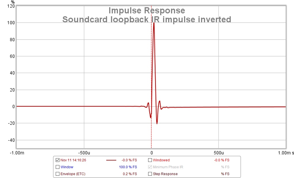
This was presumably taken with the mic gain dialed way back because of the direct line level input. However, the fact that I had to invert the impulse to get it to point up suggests I might have a polarity swap in the cable. The cable with the swap, if any, is used as the reference loopback cable so I don't think an inversion really matters there.
APL tells a different story. First with the mic gain set just below clipping we see a pretty picture with a ghost out at 26 ms:
with reduced mic gain, the ghost is reduced:
In Karaoke mode, a portion of the mic input is blended into the line output. What if the karaoke mode switch is electronic and simply switches the blending factor to high attenuation. It seems that would set up a feedback loop. OTOH, the delay to the ghost is >> the period of the ringing.
When measuring with APL, I reduce mic gain or it literally howls but when measuring with REW I need to turn it up or REW complains about low input level. This would exaggerate the problem. The one knob I didn't play with this morning was MIC gain because I wanted to keep the signal level in the sweet spot.
OK back to the lab...
When I do a line level loopback test with REW I don't see any ringing in the IR:
This was presumably taken with the mic gain dialed way back because of the direct line level input. However, the fact that I had to invert the impulse to get it to point up suggests I might have a polarity swap in the cable. The cable with the swap, if any, is used as the reference loopback cable so I don't think an inversion really matters there.
APL tells a different story. First with the mic gain set just below clipping we see a pretty picture with a ghost out at 26 ms:
with reduced mic gain, the ghost is reduced:
In Karaoke mode, a portion of the mic input is blended into the line output. What if the karaoke mode switch is electronic and simply switches the blending factor to high attenuation. It seems that would set up a feedback loop. OTOH, the delay to the ghost is >> the period of the ringing.
When measuring with APL, I reduce mic gain or it literally howls but when measuring with REW I need to turn it up or REW complains about low input level. This would exaggerate the problem. The one knob I didn't play with this morning was MIC gain because I wanted to keep the signal level in the sweet spot.
OK back to the lab...
Attachments


New XO done
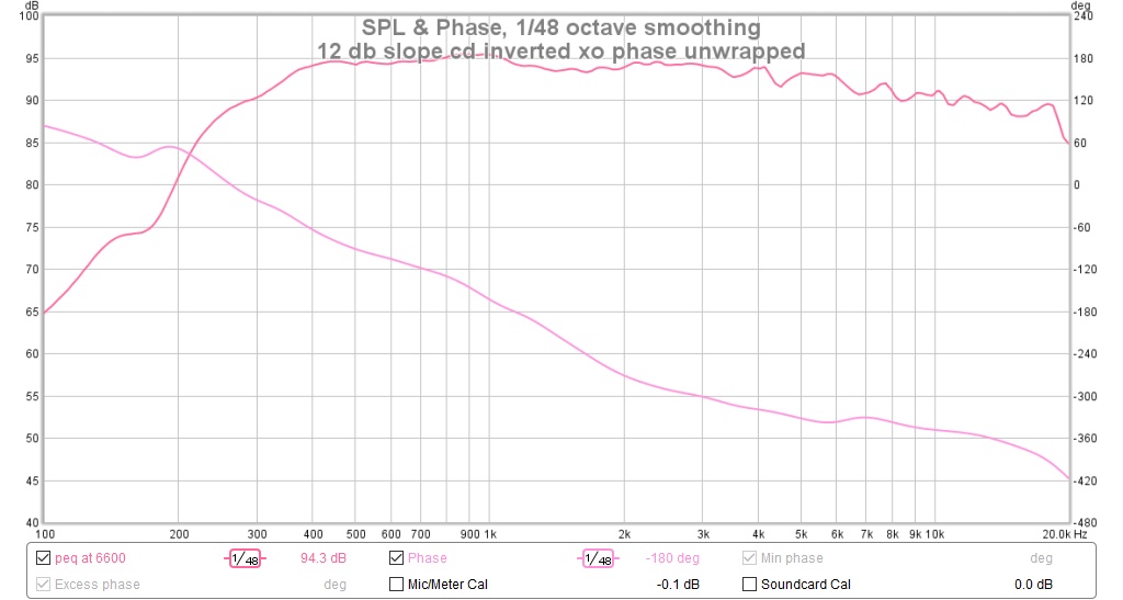
Well, I'm a believer in target slopes now. Here is a new XO with 24 db acoustic slopes in the mid-CD xo, for the first 10 db or so, after which both drivers slopes get steeper.
I'm calling this a CD inverted crossover because I have to invert the CD in the DSP to get the mid and CD impulses in phase. I must have an inversion in one of my balanced cables and I think the previous XO probably had the cd acoustically inverted.
Here is the frequency response and unwrapped phase:
Here is the IR:
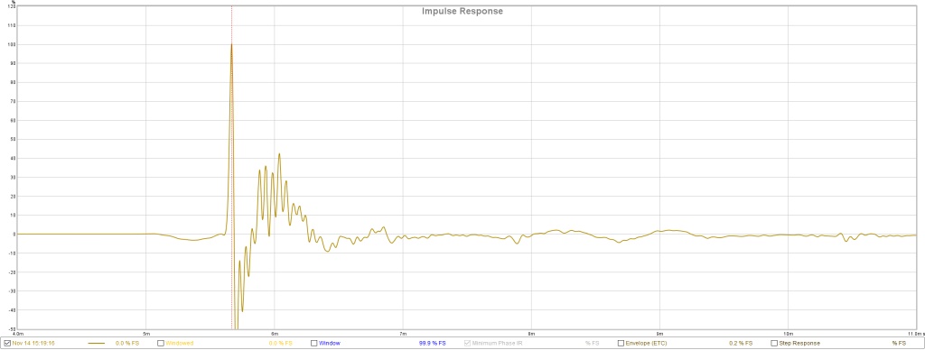
The IR still has ringing in it. Its still there when I unplug the reference loopback, which doesn't completely let the sound card off the hook because it could still be internal feedback through the mixer circuit. Fortunately, its not so strong in the filtered single driver measurements used for time alignment.
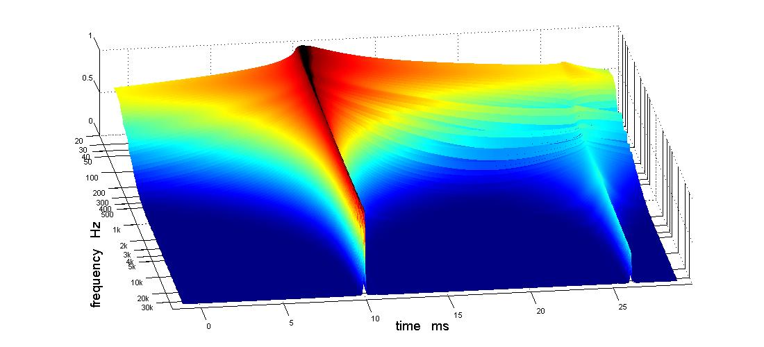
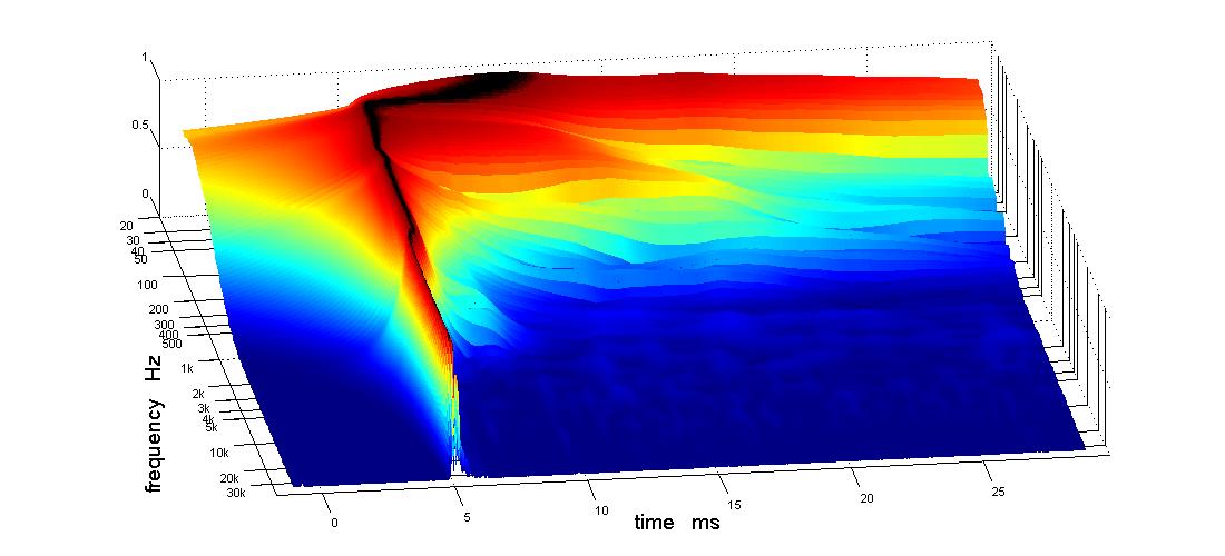
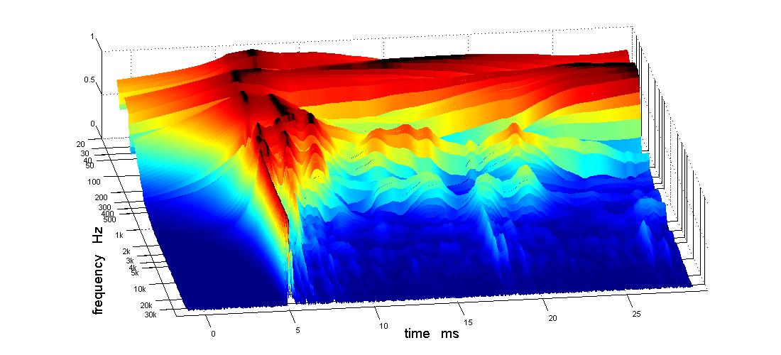
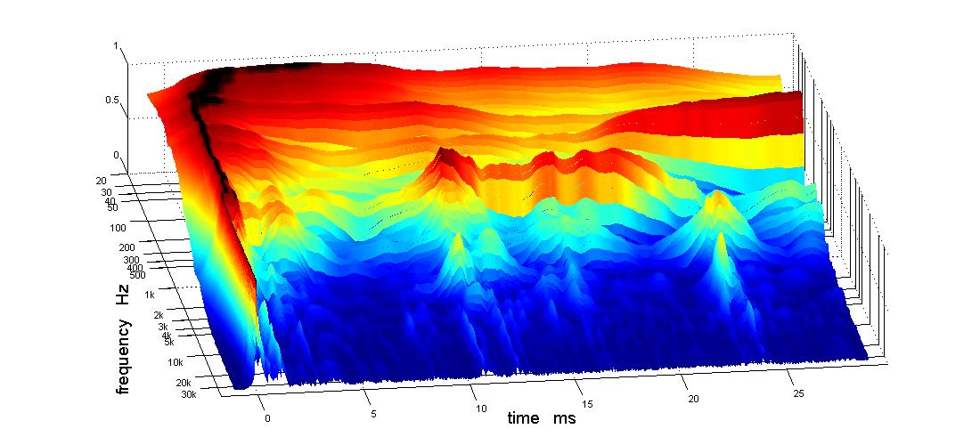
Here is the APL_TDA 3D view at 1m:
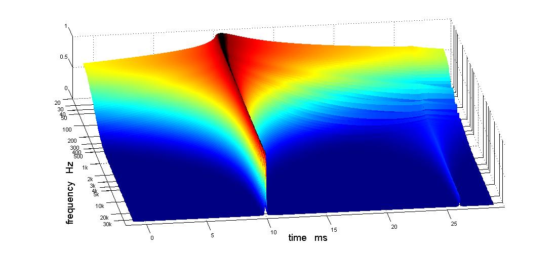
and the 2d view:
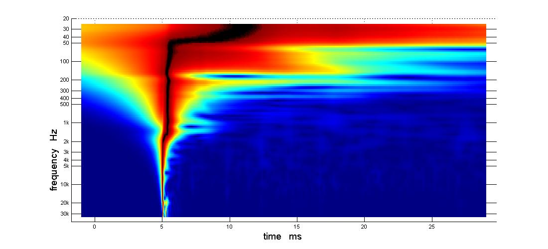
The "bend" in these pictures has straightened out and what remains moved up in frequency to where I filled in a dip. The phase isn't flat but this is still just IIR. I haven't done any FIR yet.
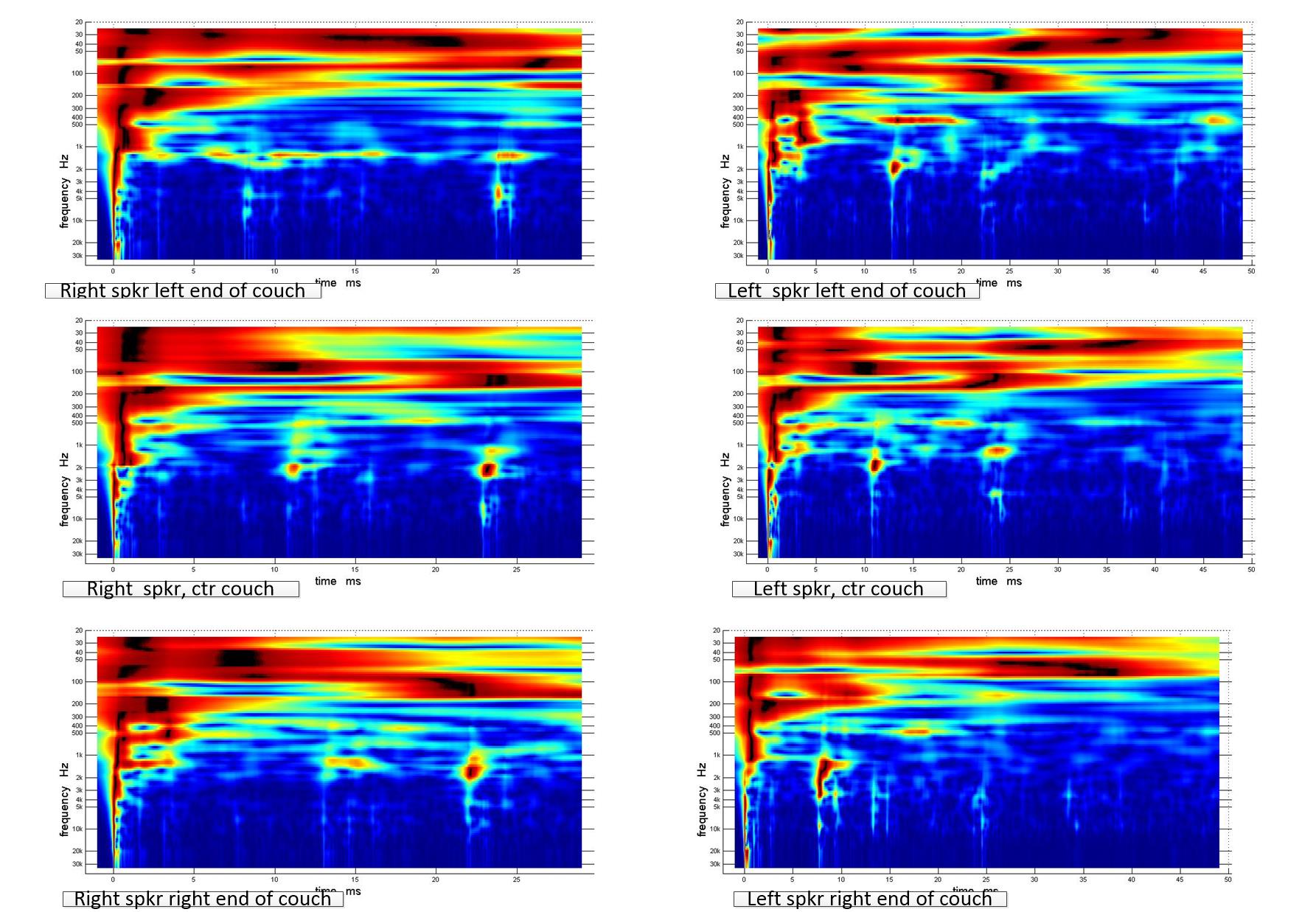
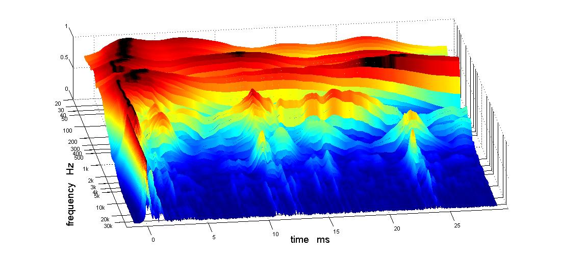
The picture is not quite so pretty out at the LP. Right end of couch:
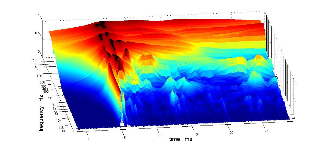
and left end of couch:
Well, I'm a believer in target slopes now. Here is a new XO with 24 db acoustic slopes in the mid-CD xo, for the first 10 db or so, after which both drivers slopes get steeper.
I'm calling this a CD inverted crossover because I have to invert the CD in the DSP to get the mid and CD impulses in phase. I must have an inversion in one of my balanced cables and I think the previous XO probably had the cd acoustically inverted.
Here is the frequency response and unwrapped phase:
Here is the IR:
The IR still has ringing in it. Its still there when I unplug the reference loopback, which doesn't completely let the sound card off the hook because it could still be internal feedback through the mixer circuit. Fortunately, its not so strong in the filtered single driver measurements used for time alignment.
Here is the APL_TDA 3D view at 1m:
and the 2d view:
The "bend" in these pictures has straightened out and what remains moved up in frequency to where I filled in a dip. The phase isn't flat but this is still just IIR. I haven't done any FIR yet.
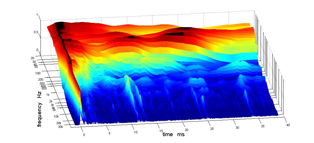
The picture is not quite so pretty out at the LP. Right end of couch:
and left end of couch:
Attachments
-
 12 db slope cd inverted xo phase unwrapped.jpg102 KB · Views: 543
 -
 tda 3d 24 db acoustic cd inverted xo.jpg55 KB · Views: 562
 -
 tda 2d 24 db acoustic cd inverted xo.jpg45.6 KB · Views: 557
 -
 tda 3d 24 db acous at right lp.jpg68 KB · Views: 548
 -
 tda 3d 24 db acous at left lp.jpg67.1 KB · Views: 548
 -
 IR 24 db acoustic mid cd 350 hz woofer left at 1m.jpg64 KB · Views: 541

Is the dip between 100-200 Hz present in both speakers when measured at the listening position? I like to have that area between 100-200 Hz reasonably flat as it is an important range for the percussion.
The target slopes helped out big time to get the phase to behave better. Nice work!
The target slopes helped out big time to get the phase to behave better. Nice work!
Is the dip between 100-200 Hz present in both speakers when measured at the listening position? I like to have that area between 100-200 Hz reasonably flat as it is an important range for the percussion.
The target slopes helped out big time to get the phase to behave better. Nice work!
Thanks. Yes, the target slopes helped indeed. When I admit to using phase tracking as well you will know I'm making progress🙂
That dip in the 1m measurement is almost completely gone with a 15 ms gate and doesn't quite hit full depth until >25 ms. Same behavior out at the LP, where there is a dip in that range but at lower frequency. It would almost have to be an opposite sidewall reflection to behave that way, wouldn't it? The room is 15.5' wide by 21' long and 8' high.
When I last posted 6 weeks, I had just redone the XO and straightened out the phase. Measurements at 1m were nice; out at the LP not so nice. I needed some room treatment
I spent a lot of time staring at APL_TDA plots trying to understand what I saw.
The red/black horizontal streaks are room modes; vertical white lines are reflections. I have some heavy LF room modes that are pretty much the same across the listening couch. This means they are longitudinal modes. I confirmed this by pushing the mic 2' forward. Things immediately got better because I had been sitting in a null of the circa 180 hz null.
That was very encouraging! But I didn't want to move the couch so close. Instead I put my absorber panels on top of the speakers across the corners to act as bass traps.

The TDA 3D center couch with bass traps is not quite as good as just moving the mic forward 2' at the center of couch but still much better than w/o the bass traps.
I got the next and final (for now) increment of improvement by equalizing the modal peaks at 80 and 200 Hz. Why not? these are longitudinal modes and I have a single row of seating.
As you can see, attenuating those peaks, helped the direct response standout above the room as it does now down into the bass. I think that is good enough for room equalization to be successful so I'm going to try that before I do any more treatments.
But I had a max SPL accident that burned out my mic or sound card or both so I have a couple more days to wait for replacements.
(I went to reduce output level on TDA's sweep and lost the leading minus sign. Instead of down 5db from uncomfortably loud, up 35db. Yow!)
I spent a lot of time staring at APL_TDA plots trying to understand what I saw.
The red/black horizontal streaks are room modes; vertical white lines are reflections. I have some heavy LF room modes that are pretty much the same across the listening couch. This means they are longitudinal modes. I confirmed this by pushing the mic 2' forward. Things immediately got better because I had been sitting in a null of the circa 180 hz null.
That was very encouraging! But I didn't want to move the couch so close. Instead I put my absorber panels on top of the speakers across the corners to act as bass traps.
The TDA 3D center couch with bass traps is not quite as good as just moving the mic forward 2' at the center of couch but still much better than w/o the bass traps.
I got the next and final (for now) increment of improvement by equalizing the modal peaks at 80 and 200 Hz. Why not? these are longitudinal modes and I have a single row of seating.
As you can see, attenuating those peaks, helped the direct response standout above the room as it does now down into the bass. I think that is good enough for room equalization to be successful so I'm going to try that before I do any more treatments.
But I had a max SPL accident that burned out my mic or sound card or both so I have a couple more days to wait for replacements.
(I went to reduce output level on TDA's sweep and lost the leading minus sign. Instead of down 5db from uncomfortably loud, up 35db. Yow!)
Attachments


- Home
- Loudspeakers
- Multi-Way
- My Synergy Corner Horn and Bass Bins