I'm still a relatively newbie to speaker building and certainly a n00b to crossover stuff. I've unpacked a few schematics now, so I'm stepping up my complexity level a little bit now. I'm looking at the Dayton III project specifically trying to unpack exactly what everything in there does - perhaps even see a response graph of it in action if anyone has such, but I haven't found one.
Speaker Project - The D III -- 8/17/2011
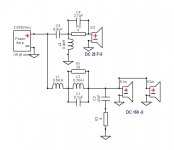
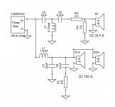
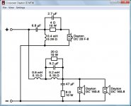
Here's the crossover schematic:
It's obviously a parallel HPF/LPF setup. I think I've got a good grasp on the tweeter. It's just a 2nd order at 2k with a zobel network in there, though I'm not exactly sure what the zobel network does. I know it 'neutralizes the effect of the voice coil inductance', but what does that mean to my ears? Does it make the ohm load (hence the volume) flatter across the spectrum, which makes it smoother? Does this ultimately lead to more detail and a crisper sound across the driver spectrum?
I'm still a bit fuzzy on the woofer stuff. The project description says it's a first order, so I presume that's what L2 is doing. The C3, L3, and R1 group look like a filter, but I'm not good enough yet to figure out the frequency, Q, dB, etc of it without finding a calculator for it. I think C4 and R2 are fiddling with the ohms, but if hooking 2 4-ohm drivers in parallel already gives you 2 ohms total, hooking another 8 ohm resistor in parallel won't give you 8 ohms to match the tweeter - it'll give you 1.6. Not really sure what's going on with that bit...?
Once I figure out what everything does in there, my next challenge is to modify the LPF to use the DC160 8-ohm drivers instead of the 4 ohm drivers. Yes, they are slightly different, I know, but they're pretty dang close. Close enough for some crossover practice, at least, I should think. Plus, I've got 4 laying on the floor collecting dust that could be making smooth tunes.
Pro tips and explanations are definitely appreciated!
Speaker Project - The D III -- 8/17/2011
Here's the crossover schematic:
An externally hosted image should be here but it was not working when we last tested it.
It's obviously a parallel HPF/LPF setup. I think I've got a good grasp on the tweeter. It's just a 2nd order at 2k with a zobel network in there, though I'm not exactly sure what the zobel network does. I know it 'neutralizes the effect of the voice coil inductance', but what does that mean to my ears? Does it make the ohm load (hence the volume) flatter across the spectrum, which makes it smoother? Does this ultimately lead to more detail and a crisper sound across the driver spectrum?
I'm still a bit fuzzy on the woofer stuff. The project description says it's a first order, so I presume that's what L2 is doing. The C3, L3, and R1 group look like a filter, but I'm not good enough yet to figure out the frequency, Q, dB, etc of it without finding a calculator for it. I think C4 and R2 are fiddling with the ohms, but if hooking 2 4-ohm drivers in parallel already gives you 2 ohms total, hooking another 8 ohm resistor in parallel won't give you 8 ohms to match the tweeter - it'll give you 1.6. Not really sure what's going on with that bit...?
Once I figure out what everything does in there, my next challenge is to modify the LPF to use the DC160 8-ohm drivers instead of the 4 ohm drivers. Yes, they are slightly different, I know, but they're pretty dang close. Close enough for some crossover practice, at least, I should think. Plus, I've got 4 laying on the floor collecting dust that could be making smooth tunes.
Pro tips and explanations are definitely appreciated!
OK on the tweeter, the 4R is for attenuation, and the 2.7uF in parallel with it means that at higher frequencies it is NOT attenuated. This is probably to bring up a drooping top end.
On the woofer the LCR is a notch filter I'm not going to take a guess as to the frequency but it is probably for taming breakup.
C4 R2 is actually a zobel and will be flattening out the naturally rising impedance of the woofer.
Tony.
On the woofer the LCR is a notch filter I'm not going to take a guess as to the frequency but it is probably for taming breakup.
C4 R2 is actually a zobel and will be flattening out the naturally rising impedance of the woofer.
Tony.
The resistor and capacitor in the tweeter circuit are there to lift the higher frequencies somewhat. Zobel compensation refers to making an impedance consistent with frequency (resistive looking), and C4 and R2 appear to be an example of this kind of thing. In this kind of use they would only achieve this with regards to the load seen by the filters, and the speaker as the load.. in other words while Zobel compensation could be used anywhere, this is the limit of this implementation. It is used either for helping to get a certain response or for simplifying design by creating a simple load to calculate for.
The RLC combination is reducing the response at 3k7Hz, maybe to do with cone breakup? The L and C set the resonance and the resistor sets a limit for the effect.
The RLC combination is reducing the response at 3k7Hz, maybe to do with cone breakup? The L and C set the resonance and the resistor sets a limit for the effect.
Try XSim to simulate your crossover. Parts-Express has FRD and ZMA files for all Dayton drivers which you can import to XSim.
This is a fantastic and free experimentation and learning laboratory. Play with it for a week and next year you'll be selling speakers at the Rocky Mountain audio festival.
Best,
Erik
This is a fantastic and free experimentation and learning laboratory. Play with it for a week and next year you'll be selling speakers at the Rocky Mountain audio festival.
Best,
Erik
Ahh! Thanks for the input! I knew I was somewhat close, but it seems to make more sense now. Thanks all!
Thanks for the reminder on Xsim too, Erik. I had fiddled with that once upon a time, but couldn't find it on my computer the other day when I went to sim all of it out. I went back to the excel version, but I like Xsim much better. Good to have a fresh link again!
Thanks for the reminder on Xsim too, Erik. I had fiddled with that once upon a time, but couldn't find it on my computer the other day when I went to sim all of it out. I went back to the excel version, but I like Xsim much better. Good to have a fresh link again!

That's much better. Remember you can use the ground symbol to reduce the wiring. Just remember to connect the amp (-) as well as the speaker (-) to it. This reduces maintenance as you move things around and cleans up the schematic. It's up to you whether you like that style or not though.
That's quite a low-treble peak there.
Without measurement it's hard to tell, but you probably need to add 1.3" or so to the woofer distances to get the phase matching correct. I'm not sure if this is mentioned in the original article. For more information, see here.
For another MTM design, since I'm close with the author, see the LM-1C here.
Best,
Erik
Just remember to connect the amp (-) as well as the speaker (-) to it. This reduces maintenance as you move things around and cleans up the schematic. It's up to you whether you like that style or not though. That's quite a low-treble peak there.
Without measurement it's hard to tell, but you probably need to add 1.3" or so to the woofer distances to get the phase matching correct. I'm not sure if this is mentioned in the original article. For more information, see here.
For another MTM design, since I'm close with the author, see the LM-1C here.
Best,
Erik
@ kc, play with the values a bit. You might find some useful gains changing the first woofer inductor and the tweeter resistor. The lower peak might be the result of the woofer resistor across the tuned filter or the tweeter high pass components.
@ erik, any suggestions on displaying multiple traces in xsim?
@ erik, any suggestions on displaying multiple traces in xsim?
A graph with individual drivers contributions would be helpful as well, As would a graph with the tweeter polarity reversed (to see how well phase is tracking).
Have you put in values for the DCR of the coils?
Certainly since the woofer measurement won't have any baffle step factored in I would think that if this sim is accurate these would be very thin and bright sounding speakers...
Tony.
Have you put in values for the DCR of the coils?
Certainly since the woofer measurement won't have any baffle step factored in I would think that if this sim is accurate these would be very thin and bright sounding speakers...
Tony.
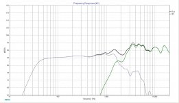
I haven't done anything fancy with baffles, distancing, or any of that jazz. I just wanted to sim the original XO to see what it looked like. Unless baffling plays a much greater part in tweeter frequencies than I thought, I really expected it to look much smoother. Those are quite the speed bumps around the XO frequency on the original design!
Thanks for the updated version Lojzek! That looks much easier and cheaper to boot! I'll definitely fiddle around with it some more once I get home tonight and maybe see about whipping up a DC160 4-ohm version too.
Thanks for the updated version Lojzek! That looks much easier and cheaper to boot! I'll definitely fiddle around with it some more once I get home tonight and maybe see about whipping up a DC160 4-ohm version too.
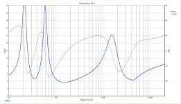
Maybe put a 0.5 to 1.0 Ohm resistors on L1 & C2 to keep the impedance tips from going quite so far down?
Very nice work Lojzek! How did you go from the Dayton files to XSim? Seems like you used some box simulation to alter the original FRD and ZMA files?
Lastly, what did you use for driver distances? Was this from the box simulator, or a guesstimate?
Thanks!
Erik
Very nice work Lojzek! How did you go from the Dayton files to XSim? Seems like you used some box simulation to alter the original FRD and ZMA files?
Lastly, what did you use for driver distances? Was this from the box simulator, or a guesstimate?
Thanks!
Erik
I wouldn't know about the nice work, it may look good on-axis in a sim,
reality is a different matter. Driver distances were like on a drawing
from Dayton 3 MTM. I've loaded the files to Jeff's Response Modeler
where baffle and box tuning were calculated in. Impedance file from PE
served a purpose as a model to which I have created a new ported one
to match the original inductive reactance by overlaying one over the other.
Woofers were delayed by a guesstimate. Now I see the acoustic origins
od DA drivers are specified in each frd.
Well, to be fair I think I have to defend the Dayton III speaker here.
Perhaps drivers and crossover are not outstanding, but they are way better than the poor data files provided by Dayton Audio. Many of them are wrong in level and show a ragged frequency response, most probably due to not flush-mounted drivers. These files are responsible for the bad result in Lojzek's simulation.
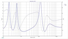
My simulation of the speaker (using Zaph's driver measurements) looks more or less decent.
Perhaps drivers and crossover are not outstanding, but they are way better than the poor data files provided by Dayton Audio. Many of them are wrong in level and show a ragged frequency response, most probably due to not flush-mounted drivers. These files are responsible for the bad result in Lojzek's simulation.
My simulation of the speaker (using Zaph's driver measurements) looks more or less decent.
Attachments
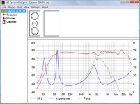
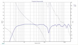
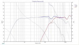
Alrighty, so I think I've got a decent design that gets me pretty close to the original simulation, but with 4-ohm drivers. Plus, I smoothed some stuff out a little bit, so the midrange looks like it should be slightly more pronounced than the originals.
Here's my schematic, along with response and impedance plot.

Those of you with a keen eye will notice the 8 ohm resistor on the tweeter isn't hooked up in the schematic. I did this intentionally to match the 'footprint' of the original design. If I hook it up, it brings the tweeter down in line with the midrange to look like this.

Here's my schematic, along with response and impedance plot.
Those of you with a keen eye will notice the 8 ohm resistor on the tweeter isn't hooked up in the schematic. I did this intentionally to match the 'footprint' of the original design. If I hook it up, it brings the tweeter down in line with the midrange to look like this.
Perhaps drivers and crossover are not outstanding, but they are way better than the poor data files provided by Dayton Audio. Many of them are wrong in level and show a ragged frequency response, most probably due to not flush-mounted drivers. These files are responsible for the bad result in Lojzek's simulation.
My simulation of the speaker (using Zaph's driver measurements) looks more or less decent.
Ah that explains things!
I had put the dayton files into speaker workshop (without doing any minimum phase extraction) and was thinking something looked very screwy. Especially on the tweeter! The bass curve did look like there was some BSC factored into the crossover.
I was going to make the comment that the crossover was probably designed with completely different measurements, or was just completely wrong.
Using the unaltered measurements from dayton, I found quite big changes were needed to get something even vaguely acceptable looking
Tony.
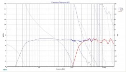
Dayton Audio seems to have made a mistake creating frd files of
DC28F-8 making it look like 93dB/2,83V/1m when they
say in general specs to be 89 dB/1W/1m. Referenced to 2,83V
would still be only 90,7 dB.
RS28A-4 has got a more powerful motor, is more than twice as expensive,
yet of lesser sensitivity, which is evident that something went wrong with
measurement files of a cheaper tweeter.
This is simulated with Zaph's measurements and original Dayton filter.
Attachments
- Status
- This old topic is closed. If you want to reopen this topic, contact a moderator using the "Report Post" button.
- Home
- Loudspeakers
- Multi-Way
- Help breaking down the Dayton III crossover