karoly7603, or whatever I must call you. I prefer first names. ")
Can I commend downloading a simulator like:
Downloads
And importing some suitable projects into the projekte folder and playing with them.
http://boxsim-db.de/kategorie/systeme/drei-wege/
I can hardly keep up with some interest that creeps from a B&W design to a Pioneer design. My own opinion, after a lot of listening, is that a flat impedance presented to our imperfect amplifiers makes for a smoother sound. Hence I would add a 22R resistor shunted across the B&W tweeter here. Possibly does more than any exotic components.
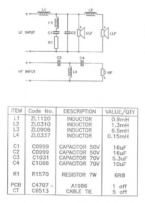
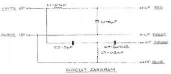
I found a schematic that would attach. So here is a Klipsch RF82 three driver two way with two inductors in the bass section of the crossover. Could the connection point of one of the woofers be placed in between the two inductors (just in front of the 0.68mH coil) and make a 2.5 way? Thanks.
Attachments
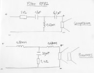
I found a schematic that would attach. So here is a Klipsch RF82 three driver two way with two inductors in the bass section of the crossover. Could the connection point of one of the woofers be placed in between the two inductors (just in front of the 0.68mH coil) and make a 2.5 way? Thanks.
You would have to reverse positions of the inductors so that the bigger one is in the middle.
Edit: Misread the values. Generally for the .5 driver (8 ohm) the inductor is going to be over 1.5 mH, depending on the baffle width.
Last edited:
No you can't simply change the connection of one woofer. Currently you have a 2-way with an 18dB/octave lowpass filter.
Changing the connection of one of the woofers will achieve 12dB/octave low pass but the crossover point and Q will be totally wrong, along with the inductor now performing the baffle step role also being the wrong value.
Even if it did work out (it won't) the woofers would be 90degrees out of phase alignment with the tweeter due to changing from a 3rd order to 2nd order lowpass filter.
If the current design has no baffle step and you'd like to add it, you'd probably be best off attempting to add a seperate baffle step compensation filter on the input of the existing crossover. This way you won't disrupt the operation of the existing crossover too much. The way i'd do it though is to add an additional BSC inductor in series with one woofer and then all the other values need to be recalculated because the lowpass filter will now see a different impedance at the crossover frequency.
Last edited:
12db/oct or 18db/oct for a tweeter
Hello
I have a Monacor DT-254 tweeter. Sounds well with the 12db/oct. filter. Nowadays I am thinking to make a 18db/oct. My question is the 18db/oct sounds better? Or what is the difference between them in sound? I don't know why but I feel that with a 18db/oct filter could sounds clearer and more separate? Maybe only this is my theory...
Thank you for your help/suggestion and information about it.
Best regards,
Karoly
Hi Karoly. If you add a component to change your filter from 12 to 18dB/8ve the main difference you will hear is the different frequency response, partly because of the changed response of each driver, partly because of the phase which would change the addition between the drivers and can also change the room reflections due to the nature of the lobing that results.
If you construct a careful, measured 12dB crossover and a careful 18dB one, the difference should be small. The main reason for using a higher order filter is to prevent the drivers from doing something they may have a problem with.
If you construct a careful, measured 12dB crossover and a careful 18dB one, the difference should be small. The main reason for using a higher order filter is to prevent the drivers from doing something they may have a problem with.
I don't think you can answer that without knowing the whole speaker.Hello
I have a Monacor DT-254 tweeter. Sounds well with the 12db/oct. filter. Nowadays I am thinking to make a 18db/oct. My question is the 18db/oct sounds better? Or what is the difference between them in sound? I don't know why but I feel that with a 18db/oct filter could sounds clearer and more separate? Maybe only this is my theory...
Thank you for your help/suggestion and information about it.
Best regards,
Karoly
I generally prefer third order as a good compromise between steep and shallow filters. A lot of people like shallow filters, but I find them fatiguing albeit lively. If you're lucky, it works as 90 degree BW3, which not only has acceptably low distortion, but good dispersion without a midrange hole off-axis and power response. FWIW, a lot of second-order bass filters are really third order with voice-coil inductance included.
Phase-alignment and frequency response is over-rated IMO. Get the power response and dispersion right. But good modelling required. Here's a flat power, 90 degree phase BW3 design, 8" plus cone tweeter idea. Look! No midrange nulls off-axis! My best effort to date. I do adjust the resistance in the bass shunt for different Le inductance drivers. Easy enough.
Attachments
Just a placemarker for later.
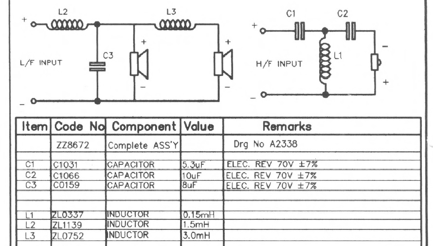
Here's the DM 630i you like:
Here's the 630 that you don't think so much of:
I don't know if the drivers are the same. But both that famous old negative polarity BW3 design.
Could you please clarify this.
I have DM630 N (at least that's what it says on the speaker bind). I opened it to check out the crossover network, and I see 3 caps, 10uf 5.3uf 8uf. According to this information you provided, this must be DM630i.
I always thought my DM630 is the original "N" version, not the updated "i" version... but looking at your post and my crossover... it appears that mine is DM630i.
Question : is there a mark elsewhere on the speaker for that "i" indicator?
I've forgotten what we're trying to do here...Could you please clarify this.
I have DM630 N (at least that's what it says on the speaker bind). I opened it to check out the crossover network, and I see 3 caps, 10uf 5.3uf 8uf. According to this information you provided, this must be DM630i.
I always thought my DM630 is the original "N" version, not the updated "i" version... but looking at your post and my crossover... it appears that mine is DM630i.
Question : is there a mark elsewhere on the speaker for that "i" indicator?
Maybe get rid of the lumpy 2.5way bass?
I'd suggest you short out the 3mH coil on the second bass with a bit of 15-30A fusewire soldered across it, then allowing for a 4 ohm B&W tweeter, and the doubled basses, it just looks like a conversion to MMT of the old 8" plus 1" KEF Celeste III. A respectable design.
Attachments
x.5 way design
Looking for some help on a much simpler 1.5 way design using two similar drivers (1 full range and one mid bass). I understand the sound waves and bsc pretty well, but not the electrical part.
I want to essentially build a full range but add a midbass for baffle step. I have two 4 ohm dayton drivers in mind.
Now because there is no tweeter the sensitivity of the 2 doesn't matter. But being 4 ohms I assume that I should do series to get 8 ohms.
Then how do I roll off one? I assume I use a capacitor in parallel with the one I want to roll off. But then my QUESTION is how does the rising impedance of this woofer affect the roll off? Also how to I pick the value.
If I had two 8 ohm woofers I'd do them in parallel and add an inductor in series, this would give the same -6db/octave effect. Again is it this simple or do I have to find flat impedance woofers to avoid a peakey response.
Bass driver https://www.parts-express.com/pedocs/specs/290-212-dayton-audio-nd105-4-specifications.pdf
2 identical drivers in series with one having a shunt cap to roll it off gives you a 1.5 way system with no baffle step gain (unless you are using a current amp. You get 3 dB extra because of 2 drivers, but double impedance means you lose 3 dB becaus ethe amplifier is outputting half at the lowest frequencies.
http://www.planet10-hifi.com/downloads/Dual-Driver-Wiring.pdf
Having different drivers with different sensitivities complicates thing.
dave
http://www.planet10-hifi.com/downloads/Dual-Driver-Wiring.pdf
Having different drivers with different sensitivities complicates thing.
dave
2 identical drivers in series with one having a shunt cap to roll it off gives you a 1.5 way system with no baffle step gain (unless you are using a current amp. You get 3 dB extra because of 2 drivers, but double impedance means you lose 3 dB becaus ethe amplifier is outputting half at the lowest frequencies.
http://www.planet10-hifi.com/downloads/Dual-Driver-Wiring.pdf
Having different drivers with different sensitivities complicates thing.
dave
Hi Dave. The link was very helpful. It seems that the reality is that you can't do a +3db baffle step simple circuit with either series or parallel with typical solid state amps. It must be +6db (parallel) or 0db (series). Now I suppose that one could pick a more or less efficient driver as the one rolling off, but this probably complicates things. As would using an l-pad to pad down one of the drivers?
As far as the impedance, doing two full ranges in series with a capaciitor, will cause the roll off to increase as the impedance rises. So the slope increases, and it works better, which is generally a good thing. Using a inductor in parallel has the opposite effect.
One thing I notice is that the chart says the typical tube amp has a +3 db increase with the drivers in series. Now I assume this is because the impedance of the amp changes with the circuit, so this only works for tube amps?
You wrote, "Can also be done actively by driving each driver with a
seperate amplifier and low-passing one. Controlling the gain
of the amplfiers also gives finer control of the relative LF/HF
levels"
This is what I do for the time being. I use a PC and equalizer APO to precisely control two different drivers. I have to say IMO that two drivers playing together in harmony is really excellent. In theory it would have lesser distortion, and I think it does, also good dynamics.
However I have to also point out that it took a lot of massaging to get them to meld into one single sound source, even with careful selection of the two drivers. Getting the same result with a passive set up might not be possible. Still, using a PC is like cheating.
Last edited:
One thing I notice is that the chart says the typical tube amp has a +3 db increase with the drivers in series. Now I assume this is because the impedance of the amp changes with the circuit, so this only works for tube amps?
Most tube amps, and particularily SE amps tend to have a high output impedance. As the impedance of the amp approachs the impedance of the speaker a greater amount of the impedance curve is convolved with the power output. This is not resistricted to tube amps — or a necessary characteristic of a tube amp — but high output impedance SS power amps are the exception (one example is some of the Firstwatt/PASS amps).
In theory it would have lesser distortion, and I think it does, also good dynamics.
Less distortion because the excursion is ¼ of a single driver, better dynamics because you can more more air. Be wary of 2 drivers runnign together at higher frequencies as you get a certain amount of combing.
dave
Series connection 1.5 way
Dave
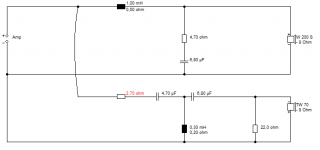
Is this the way it works and looks when modelled with 4 ohm FR drivers?
2 identical drivers in series with one having a shunt cap to roll it off gives you a 1.5 way system with no baffle step gain (unless you are using a current amp. You get 3 dB extra because of 2 drivers, but double impedance means you lose 3 dB because the amplifier is outputting half at the lowest frequencies.
Dave
Is this the way it works and looks when modelled with 4 ohm FR drivers?
Attachments
As long as it is within ¼ wavelength C-C at the XO point it will make little difference. If it is much greater you will start to get lobes.The drivers may not work together as well to look like a single driver in the lowest frequencies.
With this XO/filter is does not matter where you set the changeover — unlike the parallel arrangement where you are trying to target the baffle step F(3). Excursion in the bass is a forth that of a single driver. The amplifier is also not having to work as hard in the power hungry LFs.
dave
With this XO/filter is does not matter where you set the changeover — unlike the parallel arrangement where you are trying to target the baffle step F(3). Excursion in the bass is a forth that of a single driver. The amplifier is also not having to work as hard in the power hungry LFs.
dave
- Status
- This old topic is closed. If you want to reopen this topic, contact a moderator using the "Report Post" button.
- Home
- Loudspeakers
- Multi-Way
- 2.5 way crossover how it works?