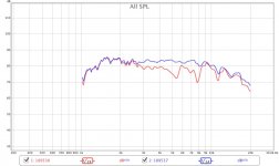
Here you can see two plots from my two Radian 475be cd's behind JMLC profile 1400 hz horns.
As you can see one of them has a problem. I asked Radian through one of their US distributors and have been told this can be a diaphragm misalignment.
Now, these are self aligning diaphragms and there is not much way to move the diaphragm. However they have told the distributor even 1/1000th of an inch matters! So, how am I supposed to align it? Does anyone know!
Attachments
There could be a number of reasons why it doesn't work like it should. For one, it could be a deformed coil/diaphragm or diaphragm mounting plate. The magnet core could be misaligned or damaged or maybe there's simply dust etc. in the magnetic gap. Another reason might be the phase correction element isn't mounted proper, worked precise, damaged or loose.
If diaphragms aren't self-aligning/centering like it should, there are a few options, depending on the way the diaphragm is mounted. I can't tell which one will work because I don't know how it's mounted (or even looks like).
One way is to use shims (i.e. stripes of paper/metal/plastic etc.). They have to have the right thickness, you place them in the magnetic gap and let them hang out outwards. Diaphragm in, mount it and pull them out one after another by loosening only one screw at a time. That will not work well for a lot of drivers though.
Another method is to place the driver on a precision turning plate (like on a lathe i.e. but horizontal) and center the driver and after that center the diaphragm the same with the measuring probe. A worker of a precision turning machine can show you how it works, there are also videos on YT where you can see how it works (don't expect them to demonstrate it on a diaphragm though).
This method will ofcourse only work if the diaphragm mounting plate is true and if there's enough space. If it isn't, then you have to turn it on a lathe true or/and build an adapter ring to mount it.
All the radian drivers I have used (no more!) use this stupid mounting scheme where the diaphragm is clamped into place with the back cap. if the screws aren't tightened evenly you get terrible response. Once you get it right (use frequency sweeps and pink noise as you adjust the tension by turning the screws) they tend to go out of adjustment and need tweeked periodically - i gave up on it - this is probably what is going on.
That sounds exactly like fitting problems. At the price of the radian Be I would not expect such problems. Once adjusted it's not a problem anymore though, you just have to use threadlocking glue/paint on the screws and the edge of the diaphragm mounting plate - problem solved.
I have read that the truextent Be diaphragms are difficult to align as well and was advised to pay extra to have them aligned by a competent technician. I was thinking about a pair in a set of JBL motors. Is that a fair assessment of the reality? I don't have any measurement gear or experience with this. Thanks and regards moray james.
i had a jbl similar to the radian diaphragm that was giving me the same issues, i used a free app to generate a 1khz sine tone from my phone and then plugged that into an amplifier and put that through the diaphragm whilst tightening it and you could hear when it was rubbing or not. it was very touchy. but i had success. Greg
i had a jbl similar to the radian diaphragm that was giving me the same issues, i used a free app to generate a 1khz sine tone from my phone and then plugged that into an amplifier and put that through the diaphragm whilst tightening it and you could hear when it was rubbing or not. it was very touchy. but i had success.
That's not the difficult part, that's the basic condition. The goal is to center it correctly in the air gap and make it lay even and tight on the whole surface of the mounting spacer, otherwise you can still get resonances and distortion at different frequencies.
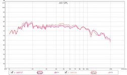
Thanks a million friends! I have solved it. I worked on screws and tried to move the backplate a little. In about 10-15 minutes it was solved")
Good news
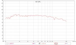
Thanks for the experience and the measurements, much appreciated. Looks like some VHF boost in the 8 to 20 kHz region would be useful, just like the large-format driver. Maybe in the 10 to 15 dB range, depending on how much ultrasonics are desired.
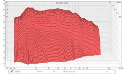
Impressive decay characteristics, though, which makes VHF boost more practical without raising audibility of a 10 to 20 kHz breakup region. Based on the measurements, there shouldn't be any aluminum or titanium breakup-mode sizzle.
Impressive decay characteristics, though, which makes VHF boost more practical without raising audibility of a 10 to 20 kHz breakup region. Based on the measurements, there shouldn't be any aluminum or titanium breakup-mode sizzle.
Last edited:
- Status
- This old topic is closed. If you want to reopen this topic, contact a moderator using the "Report Post" button.
- Home
- Loudspeakers
- Multi-Way
- How to align Radian 475be diaphragm