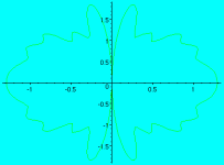
To model an open baffel that is not circular, I integrated the function
g:= (f,d,a) -> abs(1+exp(I*phi(f,d,a))); (phi is the pase shift)
that gives the gain for the two-point-source model at frequency f, distance d and angle a to average from 0.4 m to 1 m:
b:= (f,a) -> evalf( Int(g(f,d,a), d=0.4..1)/0.6);
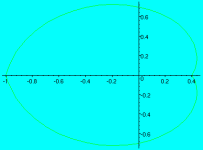
This should correspond to a baffle that is shaped like obfp1.gif:
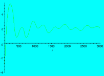
This is the frequency response on-axis from 50 to 3000 Hz:
There are a lot of peaks and holes due to interference which must be equalized. Still, this response is smoother than that of a circular baffle which has interference holes at all multiples of c/d.
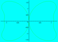
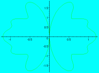
Up to 230 Hz, the radiation pattern is a figure-of-eight. This shape however becomes increasingly distorted at higher freqencies. The following graphs show the radiation pattern at 400, 800, and 1600 Hz:
At 400 Hz, there's a response of almost 2 dB at +/- 45 degrees. At 1600 Hz at lot of energy is radiated almost orthogonal to the main axis which will cause standing waves at least between floor and ceiling while other room modes are likely to be excited as well because of the lack of directivity.
My conclusion is that this baffle is useful in a range from 50 to 230 Hz only. Since it doesn't make sense to construct a different baffle for each interval, I question that open baffles are better than conventional designs. It seems that there are as many advantages as disadvantages.
Boris (yuihb01 at compuserve dot de)
Yuihb said:To model an open baffel that is not circular, I integrated the function
g:= (f,d,a) -> abs(1+exp(I*phi(f,d,a))); (phi is the pase shift)
that gives the gain for the two-point-source model at frequency f, distance d and angle a to average from 0.4 m to 1 m:
b:= (f,a) -> evalf( Int(g(f,d,a), d=0.4..1)/0.6);
This should correspond to a baffle that is shaped like obfp1.gif:
This is the frequency response on-axis from 50 to 3000 Hz:
There are a lot of peaks and holes due to interference which must be equalized. Still, this response is smoother than that of a circular baffle which has interference holes at all multiples of c/d.
Up to 230 Hz, the radiation pattern is a figure-of-eight. This shape however becomes increasingly distorted at higher freqencies. The following graphs show the radiation pattern at 400, 800, and 1600 Hz:
At 400 Hz, there's a response of almost 2 dB at +/- 45 degrees. At 1600 Hz at lot of energy is radiated almost orthogonal to the main axis which will cause standing waves at least between floor and ceiling while other room modes are likely to be excited as well because of the lack of directivity.
My conclusion is that this baffle is useful in a range from 50 to 230 Hz only. Since it doesn't make sense to construct a different baffle for each interval, I question that open baffles are better than conventional designs. It seems that there are as many advantages as disadvantages.
Boris (yuihb01 at compuserve dot de)
This is interesting, but I cannot see the images, so I'm having a hard time understanding your math. Could you post the images again?
Yuihb said:To model an open baffel that is not circular, I integrated the function
g:= (f,d,a) -> abs(1+exp(I*phi(f,d,a))); (phi is the pase shift)
that gives the gain for the two-point-source model at frequency f, distance d and angle a to average from 0.4 m to 1 m:
b:= (f,a) -> evalf( Int(g(f,d,a), d=0.4..1)/0.6);
This should correspond to a baffle that is shaped like obfp1.gif:
This is the frequency response on-axis from 50 to 3000 Hz:
There are a lot of peaks and holes due to interference which must be equalized. Still, this response is smoother than that of a circular baffle which has interference holes at all multiples of c/d.
Up to 230 Hz, the radiation pattern is a figure-of-eight. This shape however becomes increasingly distorted at higher freqencies. The following graphs show the radiation pattern at 400, 800, and 1600 Hz:
At 400 Hz, there's a response of almost 2 dB at +/- 45 degrees. At 1600 Hz at lot of energy is radiated almost orthogonal to the main axis which will cause standing waves at least between floor and ceiling while other room modes are likely to be excited as well because of the lack of directivity.
My conclusion is that this baffle is useful in a range from 50 to 230 Hz only. Since it doesn't make sense to construct a different baffle for each interval, I question that open baffles are better than conventional designs. It seems that there are as many advantages as disadvantages.
Boris (yuihb01 at compuserve dot de)
OK, before we go to the conclusions of this (which I sense that I will to some extent agree with you) I would like to get the model straight. From
g:= (f,d,a) -> abs(1+exp(I*phi(f,d,a))); (phi is the pase shift)
it seems as if you add two sources of equal magnitude. I would add four sources, but the result would be the same; on the front side we would see the point source and its mirror, and an edge reflection from the front source and also an edge reflection from the back source. Maybe you "think" four sources as well?
The back edge reflection will have the same sign as the front edge reflection, but the opposite to that of the front source and its mirror. There is a "+" in your equation above,but maybe you fix this in the phi equation?
So, how do you calculate the phase? I suppose you would calculate the pathway for each angle, first from the source to the edge, and then add the distance difference between the edge and the source, seen from the listener? Then integrate over all angles in the baffle plane to sum up all edge sources?
Do you use any directivity of the edge source? I have found this directivity kind of hard to understand from the articles I have read.
My second question is where you got the baffle shape from? Does it represent a rectangular edge distance distribution between 0.4 and 1 m or have you used some other trick? The fluctuations you see in the frequency response will vary *a lot* with the placement on the baffle, and it is likely that you could find a better baffle shape and/or placement.
A third question would be what you mean with "useful"? If you define the usefulness by that the directivity of the speaker should be a dipole, the you are right. It stops being a proper dipole at about 200Hz (for these dimensions). On the other hand I have understood that people like the dipole because it does not excite the room resonances as much as a point source. Room resonances mainly occur at low frequencies (<200Hz). Above this frequency, the baffled speaker will behave in about the same way as a boxed speaker.
I have posted this link here before, but I'll do it again in case you have not seen it. It is a little diffraction hack of mine, that allows you to experiment with different baffle shapes. It uses the model I described above, with the exception that the response is only plotted straight in front of the baffle.
http://www.tolvan.com/diffract.exe
I don't know if I answered your question, or if there was one, but anyway...
Opinions?
Baffle diffraction is fun!
Re: Re: Open baffles and directivity
My shriveled little gray cells seem to recall at least one person here who suggested that another major advantage of dipoles is the production of pseudo ambience. That would be in the range > 200Hz Yes, no?
Svante said:
On the other hand I have understood that people like the dipole because it does not excite the room resonances as much as a point source. Room resonances mainly occur at low frequencies (<200Hz). Above this frequency, the baffled speaker will behave in about the same way as a boxed speaker.
My shriveled little gray cells seem to recall at least one person here who suggested that another major advantage of dipoles is the production of pseudo ambience. That would be in the range > 200Hz Yes, no?
Konnichiwa,
Hmmm. If we assume that a flat on axis frequency response is desirable as a thing in itself - yes. But that is a preconception that is not neccesarily supportable.
Assuming of course a driver that has a perfectly omnidirectional directivity into each direction, with the baffle forming it into 2 X halvespace with opposite polarity, which in reality (rather than science fiction) of course does not happen.
Only if a driver "infinitly small" is utilised. It is quite interesting to compare a real driver with 8 - 10" Diameter under identical condition.
Your conclusion with regards to the upper useable limit is based on incomplete considerations and bad models (as in unrealistic models). Using something closer to reality gives a different picture.
Sayonara
Yuihb said:This is the frequency response on-axis from 50 to 3000 Hz:
There are a lot of peaks and holes due to interference which must be equalized.
Hmmm. If we assume that a flat on axis frequency response is desirable as a thing in itself - yes. But that is a preconception that is not neccesarily supportable.
Yuihb said:Up to 230 Hz, the radiation pattern is a figure-of-eight. This shape however becomes increasingly distorted at higher freqencies.
Assuming of course a driver that has a perfectly omnidirectional directivity into each direction, with the baffle forming it into 2 X halvespace with opposite polarity, which in reality (rather than science fiction) of course does not happen.
Yuihb said:The following graphs show the radiation pattern at 400, 800, and 1600 Hz:
Only if a driver "infinitly small" is utilised. It is quite interesting to compare a real driver with 8 - 10" Diameter under identical condition.
Yuihb said:My conclusion is that this baffle is useful in a range from 50 to 230 Hz only.
Your conclusion with regards to the upper useable limit is based on incomplete considerations and bad models (as in unrealistic models). Using something closer to reality gives a different picture.
Sayonara
Re: Re: Open baffles and directivity
What you assert makes sense, given the non-ideal nature of actual systems, but "bad models" seems a bit harsh (though you did soften it). Virtually all useful mathematical models of messy (realistic) systems begin this way. Gotta start somewhere. It's nice to see the effort given.
Sheldon
Kuei Yang Wang said:Konnichiwa,
Your conclusion with regards to the upper useable limit is based on incomplete considerations and bad models (as in unrealistic models). Using something closer to reality gives a different picture.
Sayonara
What you assert makes sense, given the non-ideal nature of actual systems, but "bad models" seems a bit harsh (though you did soften it). Virtually all useful mathematical models of messy (realistic) systems begin this way. Gotta start somewhere. It's nice to see the effort given.
Sheldon
Re: Re: Re: Open baffles and directivity
Konnichiwa,
Hmmm. Perhaps I should have said "Insufciently detailed models to draw useful conclusions", but that sounds stilted, longwinded and boring. I feel "bad model" is more to the point.
I have been repeatedly commenting that modeling speaker performance in pieces (and modeling/measuring them under anechonic conditions) is of little significance, as it failes to predict anything usefull about the actual performace in the real world. I prefer a model that is not exceptionally accurate but attempts to include at least all first order variable much more useful than one that attemps to be execissively accurate but omits virtually all first order variables....
Here some measurements taken on the (front) directivity of Dipoles.....
http://www.gmi.edu/~drussell/GMI-Acoustics/Directivity2.html
Figure2: Student measurements of radiation directivity patterns for a 3-inch loudspeaker with and without a baffle
Unbaffled speaker has a dipole-like directivity pattern
Baffled loudspeaker at 1.5 kHz (ka=0.8)
Baffled loudspeaker at 7 kHz (ka=4)
Baffled loudspeaker at 12 kHz (ka=7)
Baffled loudspeaker at 17 kHz (ka=10)
The above clearly illustrates the incorrectness of the model used. I rather have a usefull model of limited accuracy than an accurate but useless model....
Sayonara
Konnichiwa,
Sheldon said:but "bad models" seems a bit harsh (though you did soften it). Virtually all useful mathematical models of messy (realistic) systems begin this way.
Hmmm. Perhaps I should have said "Insufciently detailed models to draw useful conclusions", but that sounds stilted, longwinded and boring. I feel "bad model" is more to the point.
I have been repeatedly commenting that modeling speaker performance in pieces (and modeling/measuring them under anechonic conditions) is of little significance, as it failes to predict anything usefull about the actual performace in the real world. I prefer a model that is not exceptionally accurate but attempts to include at least all first order variable much more useful than one that attemps to be execissively accurate but omits virtually all first order variables....
Here some measurements taken on the (front) directivity of Dipoles.....
http://www.gmi.edu/~drussell/GMI-Acoustics/Directivity2.html
Figure2: Student measurements of radiation directivity patterns for a 3-inch loudspeaker with and without a baffle
An externally hosted image should be here but it was not working when we last tested it.
Unbaffled speaker has a dipole-like directivity pattern
An externally hosted image should be here but it was not working when we last tested it.
Baffled loudspeaker at 1.5 kHz (ka=0.8)
An externally hosted image should be here but it was not working when we last tested it.
Baffled loudspeaker at 7 kHz (ka=4)
An externally hosted image should be here but it was not working when we last tested it.
Baffled loudspeaker at 12 kHz (ka=7)
An externally hosted image should be here but it was not working when we last tested it.
Baffled loudspeaker at 17 kHz (ka=10)
The above clearly illustrates the incorrectness of the model used. I rather have a usefull model of limited accuracy than an accurate but useless model....
Sayonara
Re: Re: Re: Re: Open baffles and directivity
Konnichiwa,
Some more, perhaps useful observations.
This measurement was taken at 1KHz and shows the rear output having a narrower lobe and reduced rear output, to the tune of 4 - 6db.
We can see here that the directivity is controlled entierly by the drivers behaviour and due to the fact that wavelength is small compared to the drivers cone sidelobes develop. The rear radiation by now would be substantially suppressed, from experience by as much as 20db or more, depending upon the driver design.
Conclusions? The rear radiation must be modeled realistically, as must be the nature of the driver as piston at low frequencies and in most cases as bending wave transducer at higher (above theoretical pistonic range) frequencies.
In other words, the classic dipole model TOTALLY looses applicability above around 500Hz.
Of course, such things as reality and facts are of little concern if all that is desired is the defence of the orthodoxy.
Sayonara
Konnichiwa,
Some more, perhaps useful observations.
Kuei Yang Wang said:
Figure2: Student measurements of radiation directivity patterns for a 3-inch loudspeaker with and without a baffle
An externally hosted image should be here but it was not working when we last tested it.
Unbaffled speaker has a dipole-like directivity pattern
This measurement was taken at 1KHz and shows the rear output having a narrower lobe and reduced rear output, to the tune of 4 - 6db.
Kuei Yang Wang said:
An externally hosted image should be here but it was not working when we last tested it.
Baffled loudspeaker at 12 kHz (ka=7)
We can see here that the directivity is controlled entierly by the drivers behaviour and due to the fact that wavelength is small compared to the drivers cone sidelobes develop. The rear radiation by now would be substantially suppressed, from experience by as much as 20db or more, depending upon the driver design.
Conclusions? The rear radiation must be modeled realistically, as must be the nature of the driver as piston at low frequencies and in most cases as bending wave transducer at higher (above theoretical pistonic range) frequencies.
In other words, the classic dipole model TOTALLY looses applicability above around 500Hz.
Of course, such things as reality and facts are of little concern if all that is desired is the defence of the orthodoxy.
Sayonara
Re: Re: Open baffles and directivity
This is a simple two-point-source model. The rear speaker has opposite polarity (+Pi):
phi:= (f,d,a)->2*Pi*f*d*cos(a)/334 + Pi;
d*cos(a) is the retardation at angle a for a listener far away.
However, this model does not take diffraction into acount. Does it have a big impact on acoustics?
The baffle shape is a linear function in polar coordinates, as shown in ob1sp.gif. I used this as a heuristic to model non-circular or rectangular baffle shapes.
Then it would make sense to use a subwoofer-baffle while the satellites may be boxed or use smaller baffles. Boxes won't cause any trouble with interference as baffles do, but there may be resonance at 200-400 Hz. What do you think?
http://www.tolvan.com/diffract.exe
That's interesting, I'll try it when I have access to Windows again.
Svante said:
will to some extent agree with you) I would like to get the model straight. From
g:= (f,d,a) -> abs(1+exp(I*phi(f,d,a))); (phi is the pase shift)
it seems as if you add two sources of equal magnitude. I would add
This is a simple two-point-source model. The rear speaker has opposite polarity (+Pi):
phi:= (f,d,a)->2*Pi*f*d*cos(a)/334 + Pi;
d*cos(a) is the retardation at angle a for a listener far away.
However, this model does not take diffraction into acount. Does it have a big impact on acoustics?
Svante said:
My second question is where you got the baffle shape from? Does it represent a rectangular edge distance distribution between 0.4 and 1 m or have you used some other trick? The fluctuations you see in the frequency response will vary *a lot* with the placement on the baffle, and it is likely that you could find a better baffle shape and/or placement.
The baffle shape is a linear function in polar coordinates, as shown in ob1sp.gif. I used this as a heuristic to model non-circular or rectangular baffle shapes.
Svante said:
A third question would be what you mean with "useful"? If you define the usefulness by that the directivity of the speaker should be a dipole, the you are right. It stops being a proper dipole at about 200Hz (for these dimensions). On the other hand I have understood that people like the dipole because it does not excite the room resonances as much as a point source. Room resonances mainly occur at low frequencies (<200Hz). Above this frequency, the baffled speaker will behave in about the same way as a boxed speaker.
Then it would make sense to use a subwoofer-baffle while the satellites may be boxed or use smaller baffles. Boxes won't cause any trouble with interference as baffles do, but there may be resonance at 200-400 Hz. What do you think?
http://www.tolvan.com/diffract.exe
That's interesting, I'll try it when I have access to Windows again.
Re: Re: Re: Re: Open baffles and directivity
Fair enough. Thanks also for the follow on info. I appreciate any effort to quantify various effects we observe.
Sheldon
Kuei Yang Wang said:Konnichiwa,
Hmmm. Perhaps I should have said "Insufciently detailed models to draw useful conclusions", but that sounds stilted, longwinded and boring. I feel "bad model" is more to the point.
I have been repeatedly commenting that modeling speaker performance in pieces (and modeling/measuring them under anechonic conditions) is of little significance, as it failes to predict anything usefull about the actual performace in the real world. I prefer a model that is not exceptionally accurate but attempts to include at least all first order variable much more useful than one that attemps to be execissively accurate but omits virtually all first order variables....
Fair enough. Thanks also for the follow on info. I appreciate any effort to quantify various effects we observe.
Sheldon
TRANSITION FROM DIPOLE TO MONOPOLE
What is the best frequency to transition from dipole bass to monopole high frequency?
What is the best technique to make this transition?
I have been making the dipole-to-monopole transistion at 200Hz, where I use a steep crossover from the monopole mid to dipole woofer.
My baffle is "just" large enough to cover 200Hz before equalizaton for dipole baffle loss is required.
Re: Re: Re: Open baffles and directivity
Hmm... Those would be the exact lines I would write to take diffraction into account! Diffraction is the bending of the sound around the edge of the baffle. The signal that goes around the edge would be delayed just as you model it.
So, your edge reflection, seen integrated over all angles will be a rectangular pulse. This pulse will have a spectrum that will interfere with the direct impulse from the speaker. Shaping the pulse by moving the speaker and/or modifying the baffle shape can affect the spectrum and shape of the reflected pulse a lot, and so also the interference between the two.
I have little experience with open baffles, but theoretically it seems right. I cannot help thinking that dipoles is a waste of acoustic flow at low frequencies, but I am starting to understand the benefits of not exciting the room modes as much.
Yuihb said:
This is a simple two-point-source model. The rear speaker has opposite polarity (+Pi):
phi:= (f,d,a)->2*Pi*f*d*cos(a)/334 + Pi;
d*cos(a) is the retardation at angle a for a listener far away.
However, this model does not take diffraction into acount. Does it have a big impact on acoustics?
Hmm... Those would be the exact lines I would write to take diffraction into account! Diffraction is the bending of the sound around the edge of the baffle. The signal that goes around the edge would be delayed just as you model it.
Yuihb said:
The baffle shape is a linear function in polar coordinates, as shown in ob1sp.gif. I used this as a heuristic to model non-circular or rectangular baffle shapes.
So, your edge reflection, seen integrated over all angles will be a rectangular pulse. This pulse will have a spectrum that will interfere with the direct impulse from the speaker. Shaping the pulse by moving the speaker and/or modifying the baffle shape can affect the spectrum and shape of the reflected pulse a lot, and so also the interference between the two.
Yuihb said:
Then it would make sense to use a subwoofer-baffle while the satellites may be boxed or use smaller baffles. Boxes won't cause any trouble with interference as baffles do, but there may be resonance at 200-400 Hz. What do you think?
I have little experience with open baffles, but theoretically it seems right. I cannot help thinking that dipoles is a waste of acoustic flow at low frequencies, but I am starting to understand the benefits of not exciting the room modes as much.
- Status
- This old topic is closed. If you want to reopen this topic, contact a moderator using the "Report Post" button.
- Home
- Loudspeakers
- Multi-Way
- Open baffles and directivity
