Good job. Not quite done - the next step is to add back delay. I do this using interference between pairs (or even all) drivers in the system. This info allows you to determine the relative offset in the time of flight for all the drivers in the system. You don't need to know the ACTUAL delay, only the RELATIVE delay with respect to the other drivers in the system.
I rely on the interference technique and find that it is very accurate - I can determine the relative offset to within a few millimeters. The reason for designing the Blender in the first place was to make it possible to blend nearfield and farfield measurements, but you can only recover the minimum phase from the blended frequency response. Therefore you need to do this extra step.
Is it possible to approximate the delay by measuring the delta (in mm) between the woofer dust cap plane and the tweeter membrane plane?
Since you can't measure the true frequency response accurately for both high and low frequencies at the same time you have to make multiple measurements. How do you then combine amplitude and phase of these?
Exactly my question.
Hi Waly,
Several things about phase in Omnimic:
To have phase saved with files, you have to have it showing when you do the save.
Phase can't be shown if there is any "Averaging" on, so make sure that is cleared. (This is because you can't meaningfully average phase).
Omnimic phase is always time referenced to the first sound arrival at the mic (in other words, the timing will be as if the mic was placed right at the closest speaker radiating surface). That's because OmniMic works with an unattached test signal source so the software has no way of knowing what time instant the sound left a speaker. Speakers won't usually be on the same plane and their apparent distance from the mic will vary, so the best way to resolve that is by doing three measurements and using "interferometry" in effect, to find the true delay difference between them. See:
http://www.diyaudio.com/forums/multi-way/287340-xsim-critique-part-2-a-7.html#post4634286
To work with nearfield/farfield derived files, you can do the same as above, but find the delay values using "far but not too far" field measurements, and use those same values with the near and far field files (since the delay in both starts from the same first arrivals at the mic, regardless of when they left the drivers).
Last edited:
Hi Waly,
Several things about phase in Omnimic:
To have phase saved with files, you have to have it showing when you do the save.
Phase can't be shown if there is any "Averaging" on, so make sure that is cleared. (This is because you can't meaningfully average phase).
Omnimic phase is always time referenced to the first sound arrival at the mic (in other words, the timing will be as if the mic was placed right at the closest speaker radiating surface). That's because OmniMic works with an unattached test signal source so the software has no way of knowing what time instant the sound left a speaker. Speakers won't usually be on the same plane and their apparent distance from the mic will vary, so the best way to resolve that is by doing three measurements and using "interferometry" in effect, to find the true delay difference between them. See: http://www.diyaudio.com/forums/multi-way/287340-xsim-critique-part-2-a-7.html#post4634286
To work with nearfield/farfield derived files, you can do the same as above, but find the delay values using "far but not too far" field measurements, and use those same values with the near and far field files (since the delay in both starts from the same first arrivals at the mic, regardless of when they left the drivers).
Thanks, yes, I was averaging, that's why the phase was not showing. Then what is saved in the average FRD file as phase is bollocks? If so, I would rather not have it saved, rather than confusing newbies as myself.
Since you can't measure the true frequency response accurately for both high and low frequencies at the same time
You can't measure the TRUE frequency response except at the same time. If you are measuring an actual entire speaker, then I'd to measure the actual response with the actual crossover, both speakers playing, at one reasonably far mic position (or a set of positions for polar measurements).... and accept that the room and/or floor ground can't be meaningfully removed from the measurement at low frequency -- those are effectively part of the speaker unless you go to an anechoic environment (and of course anechoic measurement are only useful for comparison purposes, not too meaningful for speakers that will be listened to in a room).
Files for crossover design are of course different. I can see your point for when stuff like baffle step get into it and you need to work with phase effects that might get caused by that if they affect crossover. Then you have to synthesize that and also fix the response tails. That gets complicated by the fact that wall and floor reflections and room modal aren't far behind. I've always kept the crossover away from there (other than subwoofer, where ONLY room measurement means beans), but it need not be that way I guess.
Then what is saved in the average FRD file as phase is bollocks?
You're probably right. I didn't realize it saved anything there (it used to show all zeros). That must have crept in when I changed things to try to save a measurement phase even when the user forgets to check the box.... something I have to fix, looks like.
When you average phases, crazy stuff can happen (and not altogether determinate, as in stuff like averaging 0 and 180 degrees -- is the answer +90 or -90? Would an answer be valid or useful at all anyway?).
You can't measure the TRUE frequency response except at the same time. If you are measuring an actual entire speaker, then I'd to measure the actual response with the actual crossover, both speakers playing, at one reasonably far mic position (or a set of positions for polar measurements).... and accept that the room and/or floor ground can't be meaningfully removed from the measurement at low frequency -- those are effectively part of the speaker unless you go to an anechoic environment (and of course anechoic measurement are only useful for comparison purposes, not too meaningful for speakers that will be listened to in a room).
Files for crossover design are of course different. I can see your point for when stuff like baffle step get into it and you need to work with phase effects that might get caused by that if they affect crossover. Then you have to synthesize that and also fix the response tails. That gets complicated by the fact that wall and floor reflections and room modal aren't far behind. I've always kept the crossover away from there (other than subwoofer, where ONLY room measurement means beans), but it need not be that way I guess.
Yes, I am talking about measurements on individual drivers for the purpose of crossover design. If one is measuring a system response then things are a little different and I would just go with a single measurement and live with its limitations.
I usually do not measure phase but have it in my brain, because, as bwaslo wrote, most drivers are minimum phase, what means that their phase-versus-frequency plot can become extracted from their amplitude-versus-frequency plot. A highpass of first order shifts phase in the cut-off region rightwards (90°), a second-order highpass shifts it at first rightwards and then to the opposite of the input (180°), a third-order filter at first rightwards, then to the opposite of the input and finally leftwards (270°), and so on. Allpasses are not minimum phase because they do not change amplitude but only phase, not dampening but delaying parts of the signal. Higher-order crossovers are allpasses.
Extracting minimum phase from a finished 2-way speaker's response is almost certainly going to give you the wrong phase curves, as very few multiway speakers are actually minimum phase! You should only do that when you know that the response of the thing being measured really IS minimum phase (i.e., single driver, and a very few multiways).
I was curious to check this; I visited a neighbour running a pair of KEF coaxial bookshelves (Q1 if memory serves) and measured them. Of all multiway speakers, coaxials should definitely be close to minimum phase.
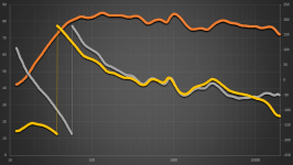
Yes indeed, the measured phase using OmniMic and the extracted minimum phase from the FRD spreadsheet are close enough. Though, I wonder where the delta in the phase jump frequency (55Hz measured, 35Hz calculated) comes from? Based on the speaker high pass ~3dB point I believe the measured phase is correct.
Orange, Gray - measured "far field" FRD (about 10cm away, pointing at the half way between the cone and the port), 250mS window
Yellow - extracted minimum phase
Attachments
Last edited:
When averaging responses wouldn't it be more usual to convert the polar magnitude and phase back to complex cartesian coordinates, average real and imag and then convert back to the polar magnitude and phase?When you average phases, crazy stuff can happen (and not altogether determinate, as in stuff like averaging 0 and 180 degrees -- is the answer +90 or -90? Would an answer be valid or useful at all anyway?).
Most coaxial driver combinations complete with cross-over are not minimum-phase. Computers are great for measuring phase, because measuring phase by old-fashioned analogue means is difficult, yet computers are not to be trusted.
Well, the KEF Q1 seems to be minimum phase
 . The match between the measured and the calculated phase is remarkable. KEF seem to target this on purpose, at least in the past:
http://www.kef.com/uploads/files/en/kef_topics/KEFTOPICS_vol2no1_a target function approach.pdf
http://www.kef.com/uploads/files/en/museum_pdf/70s/Reference_Series_Model_105_r.pdf
http://www.kef.com/uploads/files/en/kef_topics/KEFTOPICS_vol4no2_crossover filters.pdf
I believe drivers themselves are barely pure minimum phase, as long as they can barely be assimilated with a single vibrating source. I would think that waves travelling on the surface of the driver cone might become a sound source, which in turn may push the driver towards a non-minimum phase behavior.
There must be a point at which this madness should stop, otherwise we won't have any simple tools to design speakers.
- Status
- This old topic is closed. If you want to reopen this topic, contact a moderator using the "Report Post" button.
- Home
- Loudspeakers
- Multi-Way
- Measuring speakers