When I was 14 years old in 1996 I first took an interest in Hi-Fi and speakers. At the time there was no internet, but magazines and books were basically the only source of information. In Finland Pekka Tuomela was (and still is, as far as I'm considered) THE guru of these things. He had written a book called ”Build yourself Hi-Fi -speakers” that could be found in the local library.
After working my father for a year or so I got him to actually buy me an affordable speaker building kit depicted in the revered book. These kits from Tuomela's book were buyable as ready made kits (save the speaker box) from the few stores that actually sold something like DIY-speaker stuff.
The kit was a Tuomela design designated as Hifi 20/2 II, meaning a 2-way speaker in a 20 litre (5.28344 gallon) box, and the II specifying it was his second take on the design. Since the second version the box was actually 24 litres in volume instead of the original 20 litres. I made the speaker boxes during a school carpentry class. For I run out of time at schools end in spring the boxes still actually lack totally paint in the backside of the boxes.")
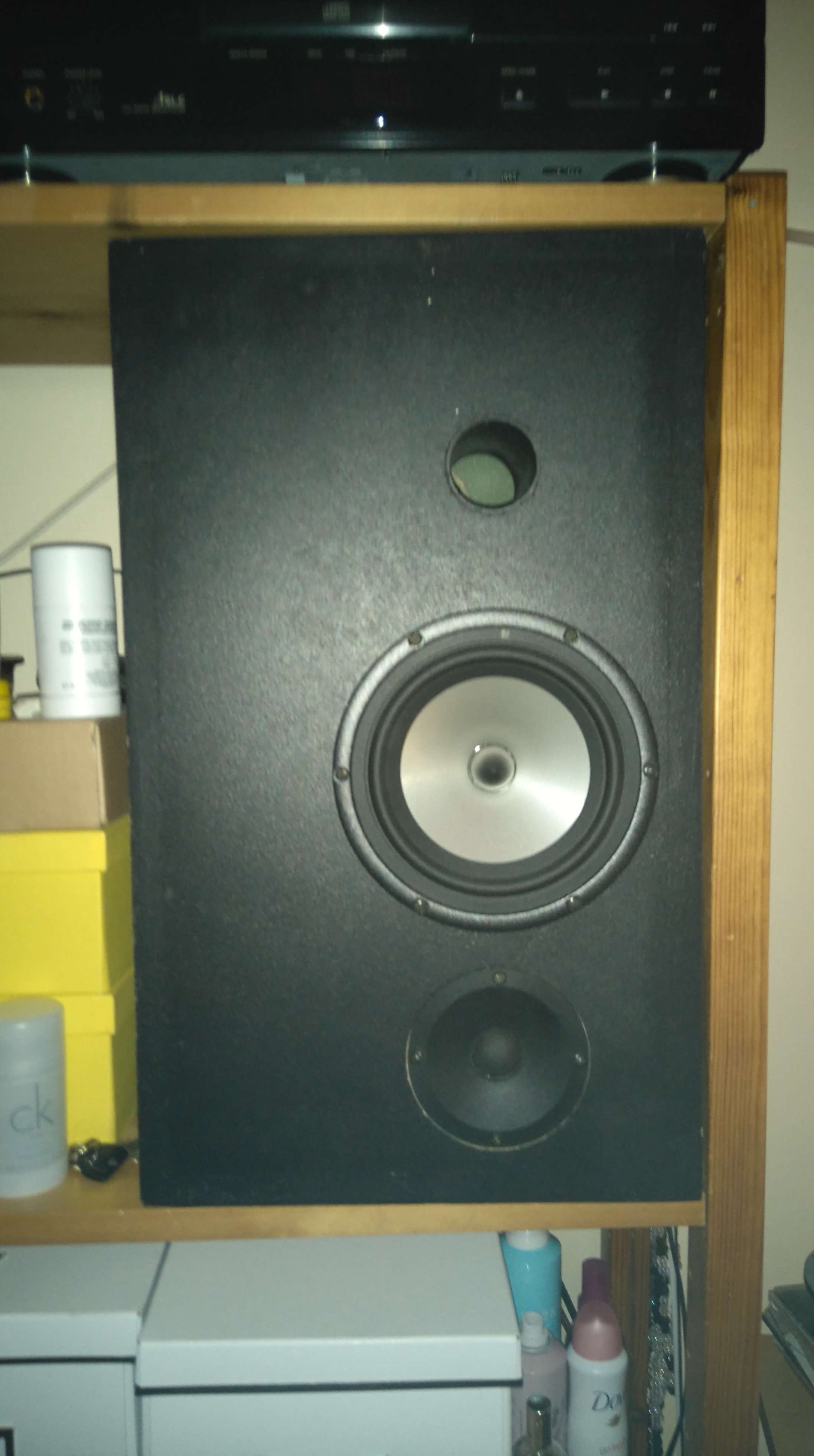
The original older design had featured a Peerless 833429 woofer and a tweeter I can't now recall. The second take, the model ”II” I had built, featured a Seas P 17 RC4 woofer, 17 cm (6,5 inches) wide polyprpylene cone woofer, and a Peerless 100DT 2672 SFWA tweeter, a 2,5 cm (one inch) textile dome tweeter. The design also featured an asymmetrical baffle (see picture). The crossover frequency was relatively high, 3500 Hz, and the tweeter polarity straight (the same polarity as the woofer in the parallel crossover design).


After happily living with these speakers about ten years and very much liking their sound, I played, as a retaliation, excessively loud music in a student apartment. This eventually destroyed the woofers (the voice coils had been dented in the heat of the night, and after a few years more of service the woofers finally gave up, I suppose).
So, in 2015 I had ”had been great speakers” with functioning tweeters and all the information about the original design (the book could be still found in a library).
So, firstly, I searched for the original woofer, Seas P 17 RC4. It was nowhere available anymore, not even from the manufacturer. Secondly, I bought a pair of Peerless 833429 woofers, used in the first, old design, naively enough thinking that they might work as such. They didn't. Secondly I read thoroughy the Tuomela book and specificly the section about bass response.
After some thought I browsed for newer Seas woofers that might work well with the box. I found Seas L18RCY/P which had similar enough specifications for the box: Free air resonance 32 → 33Hz, Qts 0,24 → 0,31, Vas 38 litres → 38 litres. I bought a pair, installed them to the speakers and listened. Horrid! Thus began the pain (and the fun).
I experimented by some guidelines from Tuomela's book, and got some ideas. I Wasn't happy though, so I ended up with WinPCD. I ended up with the FINAL design, great looking SPL curve, but it didnt sound right.
I got a microphone (an affordable USB-microphne, not a measuring mic, let alone calibrated) and measured the reasults in a regular room. Not anything I'd expected, albeit smoothing and forgiving DIY-mindset!

After measuring and experimenting I ended up with this.
I'm still considering options to even out the baffle step aroud 600-900 hz. Thinking about 1,8 mH + 2,7 ohm parallel. Any other ideas, in general or a different design?
After working my father for a year or so I got him to actually buy me an affordable speaker building kit depicted in the revered book. These kits from Tuomela's book were buyable as ready made kits (save the speaker box) from the few stores that actually sold something like DIY-speaker stuff.
The kit was a Tuomela design designated as Hifi 20/2 II, meaning a 2-way speaker in a 20 litre (5.28344 gallon) box, and the II specifying it was his second take on the design. Since the second version the box was actually 24 litres in volume instead of the original 20 litres. I made the speaker boxes during a school carpentry class. For I run out of time at schools end in spring the boxes still actually lack totally paint in the backside of the boxes.
The original older design had featured a Peerless 833429 woofer and a tweeter I can't now recall. The second take, the model ”II” I had built, featured a Seas P 17 RC4 woofer, 17 cm (6,5 inches) wide polyprpylene cone woofer, and a Peerless 100DT 2672 SFWA tweeter, a 2,5 cm (one inch) textile dome tweeter. The design also featured an asymmetrical baffle (see picture). The crossover frequency was relatively high, 3500 Hz, and the tweeter polarity straight (the same polarity as the woofer in the parallel crossover design).
An externally hosted image should be here but it was not working when we last tested it.
After happily living with these speakers about ten years and very much liking their sound, I played, as a retaliation, excessively loud music in a student apartment. This eventually destroyed the woofers (the voice coils had been dented in the heat of the night, and after a few years more of service the woofers finally gave up, I suppose).
So, in 2015 I had ”had been great speakers” with functioning tweeters and all the information about the original design (the book could be still found in a library).
So, firstly, I searched for the original woofer, Seas P 17 RC4. It was nowhere available anymore, not even from the manufacturer. Secondly, I bought a pair of Peerless 833429 woofers, used in the first, old design, naively enough thinking that they might work as such. They didn't. Secondly I read thoroughy the Tuomela book and specificly the section about bass response.
After some thought I browsed for newer Seas woofers that might work well with the box. I found Seas L18RCY/P which had similar enough specifications for the box: Free air resonance 32 → 33Hz, Qts 0,24 → 0,31, Vas 38 litres → 38 litres. I bought a pair, installed them to the speakers and listened. Horrid! Thus began the pain (and the fun).
I experimented by some guidelines from Tuomela's book, and got some ideas. I Wasn't happy though, so I ended up with WinPCD. I ended up with the FINAL design, great looking SPL curve, but it didnt sound right.
An externally hosted image should be here but it was not working when we last tested it.
I got a microphone (an affordable USB-microphne, not a measuring mic, let alone calibrated) and measured the reasults in a regular room. Not anything I'd expected, albeit smoothing and forgiving DIY-mindset!
After measuring and experimenting I ended up with this.
An externally hosted image should be here but it was not working when we last tested it.
I'm still considering options to even out the baffle step aroud 600-900 hz. Thinking about 1,8 mH + 2,7 ohm parallel. Any other ideas, in general or a different design?
Last edited:
Well, you need measurement tools you can count on. Assuming you have that, I'd say your curve is out of whack.
The first thing to do is get your drivers into XSim so you can simulate your changes instead of toying around with real parts. That's endless.
So, first, read this blog post on measuring speaker distances. Once you've done that properly, then you can simulate your current crossover and then we can talk about good sounding speaker curves.
Best,
Erik
Last edited:
I'll have to check out the XSim! Thank's for the suggestion. I have used WinPCD for that very purpose though, simulating crossover changes before actually changing the physical parts. For most changes it seems to be very accurate. For some reason it doesn't simulate well how the crossover and the tweeter affect the baffle step.
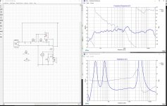
For my question in the end of the post to make any sense, here are the current crossover designs:

The mid/high frequency ring was really nasty! The series LC-circuit parallel to the woofer fixed it pretty well: 0,10 mH coil and 8,6 uF capacitor that place the circuit's resonance frequency between the worst rings at 5 and 7 kHz.
Here are the specs for the woofer and the tweeter:
H1085-08 L18RCY/P
http://imageshack.com/a/img921/4726/kNHfKS.jpg
For my question in the end of the post to make any sense, here are the current crossover designs:
An externally hosted image should be here but it was not working when we last tested it.
The mid/high frequency ring was really nasty! The series LC-circuit parallel to the woofer fixed it pretty well: 0,10 mH coil and 8,6 uF capacitor that place the circuit's resonance frequency between the worst rings at 5 and 7 kHz.
Here are the specs for the woofer and the tweeter:
H1085-08 L18RCY/P
http://imageshack.com/a/img921/4726/kNHfKS.jpg
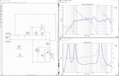
Those aren't actually the current crossovers but an older version. These are the current versions:

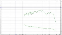
The simulation looks like this, the measurements are from the actual box from 40 cm distance to mitigate reflections. It's otherwise fairly accurate, but the baffle step above 1 kHz. in the simulation does not show up in the actual measurement.
An externally hosted image should be here but it was not working when we last tested it.
For some reason the XSim simulation (with frd-files measured in the box for both drivers, same microphone and software as in the speaker measurement) shows a big baffle step at 1 - 2 kHz but in real life it's not there. I adjusted driver delays for the simulated phase to match real life measurement.


There isn't any additional baffle step modeling in the sim, only the actual driver measurements as frd-files, measured from the box I use. :-O The baffle step shows in the woofer measurement, so it is a real life baffle step. For some reason the 1 - 2 kHz portion of the baffle step disappears in real life when I measure the speaker as whole, albeit showing distinctively in the sim.
Attachments
I think I'll have to give a go for eriksquires' suggestion of testing driver distances to include their effect to the sim.

Strange. Something is not right. I find that if the measurements are good, and everything is right in the sim that the sim and the measured result are almost identical (though I have not used Xsim)
You mention putting in driver offsets. If you have measurements with minimum phase then you will need to do this. If you have measurements that have the relative phase offsets already in them then you should not put in any offsets.
Tony.
You mention putting in driver offsets. If you have measurements with minimum phase then you will need to do this. If you have measurements that have the relative phase offsets already in them then you should not put in any offsets.
Tony.
Winter,
Yes, XSim will give you near perfect electro-acoustic simulations IF you have entered the correct driver impedance data (*.ZMA), frequency response (*.FRD) and physical offsets (mod offset).
All the driver measurements of course should be without a crossover, as mentioned in my blog posting.
If you get all these right, then designing with XSim is a breeze and very accurate.
Best,
Erik
A good sanity check (also how to work out the z offset as per Jeff bagbies procedure , is to set up the mic on axis with the tweeter.
Measure tweeter. Don't change anything, and measure the woofer. Now run both woofer and tweeter together (no crossover) and measure again.
Convert the woofer and tweeter measurements to minimum phase.
Now load the woofer and tweeter measurements into your sim, and the combined response as an overlay.
Don't put in any crossover components. Just adjust the z offset until your simmed response macthes your overlayed actual measurement of both drivers running.
The above only uses Z offset as the X and Y offsets are already present in the measurements as both were taken on the tweeter axis.
If you get a good correlation then you can trust your measurements
Tony.
Last edited:
First of all, thank you eriksquires for the reminder for using the ground symbol instead of bundling up everything to the minus/ground of the generator. I'm not so strong on electronics and ac circuits are to some extent still a mystery for me. Secondly, I agree that something is wrong in the simulation. I have a hard time fathoming what it would be, though.
I've measured the drivers in a small room and use a 1/24 octave softening. I've used a mic that really isn't state of art (altough it isn't bad either) with a piece of freeware (RoomEQWizard), so there's plenty of potential sources of error that could accumulate.
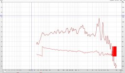
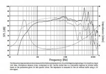
Yet, firstly, when we take a look at my measurement and the SPL curve from manufacturer spec sheet (images attached), they're at least very much in the same ballpark if not identical, save the extra spice in my measurement from the room reflections and the horizontally asymmetrical baffle.
Secondly, The simulated phase from Xsim (based on my driver measurements) is very similar to the measured phase in my measurement of the speaker as whole. I used one output and input (right) for measuring and the other input/output as a time reference as REW guide suggested to get an accurate phase. The phase used in the driver frd-files thus is the actual phase corrected using a time reference, and not a calculated minimum phase.
Based on the difference between the measured and simulated phases I introduced some latency/distance corrections into the Xsim. However, as far as the simulated SPL goes, it has very little, if any, effect. Also the phases of the simulation and the actual speaker-as-whole measurement are for the most parts quite similar. I attached images of the real world measurement, the Xsim simulation with no distance/latency changes and the "corrected" distance/latency example. Latency corrections don't really have any effect on the baffle step issue.
I've measured the drivers in a small room and use a 1/24 octave softening. I've used a mic that really isn't state of art (altough it isn't bad either) with a piece of freeware (RoomEQWizard), so there's plenty of potential sources of error that could accumulate.
Yet, firstly, when we take a look at my measurement and the SPL curve from manufacturer spec sheet (images attached), they're at least very much in the same ballpark if not identical, save the extra spice in my measurement from the room reflections and the horizontally asymmetrical baffle.
Secondly, The simulated phase from Xsim (based on my driver measurements) is very similar to the measured phase in my measurement of the speaker as whole. I used one output and input (right) for measuring and the other input/output as a time reference as REW guide suggested to get an accurate phase. The phase used in the driver frd-files thus is the actual phase corrected using a time reference, and not a calculated minimum phase.
Based on the difference between the measured and simulated phases I introduced some latency/distance corrections into the Xsim. However, as far as the simulated SPL goes, it has very little, if any, effect. Also the phases of the simulation and the actual speaker-as-whole measurement are for the most parts quite similar. I attached images of the real world measurement, the Xsim simulation with no distance/latency changes and the "corrected" distance/latency example. Latency corrections don't really have any effect on the baffle step issue.
Attachments

I've been using Jeff Bagbies WinPCD this far, and get the same anomaly with the baffle step albeit PCD gives slightly different sim results compared to the XSim. I'll really have to test out measuring the offset. I had it in mind when measuring the drivers, but eventually didn't do it because I was worried about measuring both drivers in parallel without crossovers for the possible damage to the tweeter. There's always the possibility of using a big (say 20 uF) capacitor in parallel to the tweeter, but wouldn't that introduce an approximately -90 degrees shift to the tweeters phase? I might just try measuring the drivers in parallel with as low as possible sound pressure.
The driver measurements I use were made with the mic in a fixed position a little below the tweeter axis. Tweeter and woofer were both measured with the mic in the same position.
It'll take some days though before I'll get the measurements done, for my girlfriend really isn't too fond of hearing 75 dB sine sweeps.
Open the *.zma files in notepad and ensure that phase information is included.I'll also have to measure driver impedances myself, for I've been relying on manufacturer spec sheet measurements. I'd expect them to be right, but that's also a possible source of error.
Make sure you are measuring drivers and combined drivers without the crossover, and that your simulation for speaker distance is without a crossover.
After this, adding parts to XSim will give a realistic result. If you have an existing speaker and crossover you shoudl be able to add the crossover parts to XSim and end up with the simulation and measurements being identical. You should get to the point where the speaker and XSim match precisely. Once there you can hack your schematic at will.
Are we saying the same thing?
Erik
Last edited:
- Status
- This old topic is closed. If you want to reopen this topic, contact a moderator using the "Report Post" button.
- Home
- Loudspeakers
- Multi-Way
- A daunting first (re)design