maartentje said:Okay i will scan every thing about it i think tommorow its ready to post it, i will post it on my website.
again sorry for my english
Hi Marteen,
I can't access to your website ("Directory Listing Denied"), is this normal?
No, nothing in particular. Are the P17's the one for about 3500 rupees from Shiva because I saw a couple of woofers and I dont remember the model numbers. And tell me how they sound because I bought a pair of TC18WG49 (Rs. 1575 each).
Did you listen to the floorstanders he has built? He was also saying that there were several people interested in starting a DIY audio club here in Bangalore.
Did you listen to the floorstanders he has built? He was also saying that there were several people interested in starting a DIY audio club here in Bangalore.
I'd say you *must* replace the load resistance with a better model so you see the results on the computer rather than in the real thing... You can ignore the RML component, and the others can be calculated from the T/S parameters.
Svante,
Please correct me if i am wrong...Looking at the equivalent circuit...we have..
Re = Dc resistance of voice coil. -> 5.8 ohms
Le = Inductance of voice coil -> .55mH
Bl = force factor...6.5
cms =
to get cms from vas is this equation correct.(if memory remains)?
vas/(1.4 * 10^5 * sd^2)
in that case...
with vas = 34.7L and sd = 136cm^2
is cms = 1.34 * 10^-6
Mms = 14g
Rms = hw to get this...
can i get it from terms like Qms, mms and Fo
Could some one tell me the formulas or pointers to them on the web please...!!
Thanks
ajju
ajju said:Sreten :
Interesting thought. Will explore the possibility..
Couple of questions...
1) If i have to re-tune the port how easy is it going to be.
2) Since the weight of the speaker is off axis i need to lower the
centre of gravity of the whole unit or provide a large base.
I had thought of putting a sandfill as indicated in the diagram...
How do i manage that if i were to use the centre of the base
as a part of the flare port.
ajju
1) I'm not too sure about, the main effect of exploiting the
flare I believe is that the port will sustain a higher velocity
before "chuffing", so you can use a smaller port.
2)
a) you can move the circular stand to below the C of G.
b) if the stand is rigididly fixed can't see the difference.
c) the circular stand is attached to an internal section that is not
the cabinet base.
The cabinet base has a single port surrounding the circular stand.
You can add sand in the base around the port as before.
I'll also point out you can't use a circuit simulator and electrical
models of drivers for crossover design with accurate results.
The reason for this is drivers do not add acoustically the
same way they do electrically in the crossover region.
See Linkwitz/Riley crossover alignments for further details,
and electrical targets to achieve flat acoustic results.
They also ignore the acoustic effects of the mounting of the driver.
With your suggested design diffraction effects must be considered.
") sreten.
sreten.
models of drivers for crossover design with accurate results.
The reason for this is drivers do not add acoustically the
same way they do electrically in the crossover region.
See Linkwitz/Riley crossover alignments for further details,
and electrical targets to achieve flat acoustic results.
They also ignore the acoustic effects of the mounting of the driver.
With your suggested design diffraction effects must be considered.
sreten.yes Sreten, I agree with you...
this is just a simple start...will be building up step by step...
taking inputs from all fronts....improving by incorporating necessary corrections and ofcourse by the ear...!
but only thing is time is a bit scarce now..so the progress is a bit slow...
btw...what is your opinion on the structure....
my main worry is ...will it start behaving like a massloaded TL at some mid bass freq, instead of the BR i'm intending...
in that case it is likely to generate some nasty peaks...!
so a bit confused now..!
ajju.
this is just a simple start...will be building up step by step...
taking inputs from all fronts....improving by incorporating necessary corrections and ofcourse by the ear...!but only thing is time is a bit scarce now..so the progress is a bit slow...
btw...what is your opinion on the structure....
my main worry is ...will it start behaving like a massloaded TL at some mid bass freq, instead of the BR i'm intending...
in that case it is likely to generate some nasty peaks...!
so a bit confused now..!
ajju.
ajju said:
Svante,
Please correct me if i am wrong...Looking at the equivalent circuit...we have..
Re = Dc resistance of voice coil. -> 5.8 ohms
Le = Inductance of voice coil -> .55mH
Bl = force factor...6.5
cms =
to get cms from vas is this equation correct.(if memory remains)?
vas/(1.4 * 10^5 * sd^2)
in that case...
with vas = 34.7L and sd = 136cm^2
is cms = 1.34 * 10^-6
Mms = 14g
Rms = hw to get this...
can i get it from terms like Qms, mms and Fo
Could some one tell me the formulas or pointers to them on the web please...!!
Thanks
ajju
The formula for Cms os OK, but you have to enter volume in cubic metres and area in square metres. Then you end up with Cms=1.3e-3 m/N Check: This would lead to an fs of the driver of 1/(2*pi*sqrt(1.3e-3*14e-3))=37.3 Hz, is that right?
Also, since Qms=ws*Mms/Rms, Rms=2*pi*fs*Mms/Qms. Assuming a Qms of, say 5, this would mean that Rms is 0.66 Ns/m, and that Bl^2/Rms=6.5^2 / 0.66=64 ohm.
sreten said:I'll also point out you can't use a circuit simulator and electrical
models of drivers for crossover design with accurate results.
The reason for this is drivers do not add acoustically the
same way they do electrically in the crossover region.
See Linkwitz/Riley crossover alignments for further details,
and electrical targets to achieve flat acoustic results.
They also ignore the acoustic effects of the mounting of the driver.
With your suggested design diffraction effects must be considered.
Well, *some* sort of circuit simulator must be used, right?
In what way do you mean that the drivers don't add the same way as in the electrical world? Are you talking about a delay between the woofer/tweeter? And of course, the baffle step will not be seen in this simulation. Is there anything more that I don't know of?Svante said:Well, *some* sort of circuit simulator must be used, right?
True, the good simulators add acoustic modifiers
to what is essentially a circuit simulator.
Basically the +3dB efficiency step you get with two drivers
operating together. Consideration of this phenomena led
to the Linkwitz / Riley alignments, which form no part of
classical filter theory alignments.
Simply put, 2nd and 4th order L/R alignments c/o at - 6dB
rather than the classical -3bB point. This compensates for
the parrallel efficiency increase mentioned above.
(There are no odd order L/R alignments)
sreten.sreten said:
True, the good simulators add acoustic modifiers
to what is essentially a circuit simulator.
Basically the +3dB efficiency step you get with two drivers
operating together. Consideration of this phenomena led
to the Linkwitz / Riley alignments, which form no part of
classical filter theory alignments.
Simply put, 2nd and 4th order L/R alignments c/o at - 6dB
rather than the classical -3bB point. This compensates for
the parrallel efficiency increase mentioned above.
(There are no odd order L/R alignments)
Ahh, but it works the same way with voltages! Att two in-phase voltages and you get +6 dB. Add two in-phase sound pressures and you get +6dB. The efficiency gain in the acoustic case comes from that the power to the drivers is only doubled or +3dB net gain +3dB, but that is a different issue. Adding voltages will give the same sum, like in the Linkwitz/Riley filters.
Add two 90-degree out-of-phase voltages or pressures and you end up with +3dB. Like with odd-order butterworth filters.
Right?
Svante said:
Ahh, but it works the same way with voltages! Att two in-phase voltages and you get +6 dB. Add two in-phase sound pressures and you get +6dB. The efficiency gain in the acoustic case comes from that the power to the drivers is only doubled or +3dB net gain +3dB, but that is a different issue. Adding voltages will give the same sum, like in the Linkwitz/Riley filters.
Add two 90-degree out-of-phase voltages or pressures and you end up with +3dB. Like with odd-order butterworth filters.
Right?
Sreten, are you with me on the voltages?
The formula for Cms os OK, but you have to enter volume in cubic metres and area in square metres. Then you end up with Cms=1.3e-3 m/N Check: This would lead to an fs of the driver of 1/(2*pi*sqrt(1.3e-3*14e-3))=37.3 Hz, is that right?
Svante:
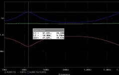
With the parameters obtained i tried to model the Equivalent circuit...
these are the results i got...
looks rather strange...
the blue line is the estimated impedence....
is this expected or is something wrong...?
Attachments
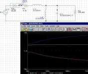
The circuit and the component values seem OK. It also looks as if the thinking behind the curves is right, you measure the current across the circuit and divide it with the current flowing into it. But the curves look strange. One reason is that you have a linear scale on the frequency axis, so the range 10-100Hz where the interesting resonance occur is *very* compressed. But that is not the whole story, the impedance should never be below 5.8 ohms, and it should peak at 5.8+18.8 ohm at 37 Hz. Towards higher frequencies it should increase indefinitely due to Le.
I don't know your simulation software, so I can't help you with that.
HTH
I don't know your simulation software, so I can't help you with that.
HTH
Basically the +3dB efficiency step you get with two driversoperating together. Consideration of this phenomena led
to the Linkwitz / Riley alignments, which form no part of
classical filter theory alignments.
Sreten:
Is the reference above to two drivers which are very similar, operating together..? Say 2 6" with same specs operating in tandem..!!
correct me if i am wrong..
In that case, i guess a good model should be able to simulate that. Because as i've read long back, and if my memory remains, there was some reference to a term called radiation resistance(acoustic) or something and an acoutic coupling coefficient...
Assume our louspeaker acts like a transformer. And the coupling between the LS and air is some function of its radiating area or the air i moves. So if we can transfer this load from the acoustic side to the electrical side we might get some parameter, say x.
With two loudspeakers connected to the same source paralelly we see a net load that is lower than if only one would have been there..am i right in saying so..
So the effective impedence seen by the source is now aproximately half as to what was earlier....
Would I be correct in that assumption...???

Svante,
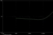
heres is a zoomed graph...both axes in log scale...
Still i dont find that characteristic peak...Is it possible that the Q is bad and the peak has flattned out...?...some parameters miscalculated...
I get a doubt...
we have ignored the Bl^2/rml component...and that comes in parallel to the bl^2/Rms resistive component...
Could that be the culprit..Oh but that would still decrease the parallel resistance...
Ok i'll alter the resistances and see if i can get the peak...
and where is it located...!
Lower the series resistance and increase the parallel one...
just an experiment..!
ajju
- Status
- This old topic is closed. If you want to reopen this topic, contact a moderator using the "Report Post" button.
- Home
- Loudspeakers
- Multi-Way
- P17WJ and D27TG into a floorstander-advice.