I will check if components are in specs, but I also think they will be OK.
Somebody recommended to replace the cored inductors with inductors without core, that will be bigger. In principle it make sense. In practice, I am not sure.
I think that the component choice will come after, as the general agreement is that the response graph should be corrected.
I am working now on drawing the schematic, I should be done in few hours.
Thanks,
Davide
It's quite a pretty speaker mechanically.
TBH, I'd view the heavy 2.5 way bass response as being potentially irritating.
Hence your tendency to block the reflex port.
But, TBH, without a schematic of the crossover, it's hard to suggest an improvement, though diyaudio.com people are good at this sort of thing. First order is all very well, but tends to high distortion with complex program material. Bi-amping is hardly going to get you out of the hole.
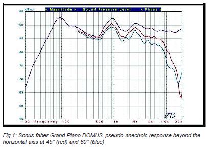
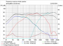
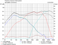
Dips like those in the FR are usually located at xo points. The HIFI Shack website listed the XO specs as 400 hz and 3600 hz. The FR dip at 400 hz. could be indicative of an out of phase wiring with the midrange. The 1.5 kHz LMS dip is inexplicable assuming the 3.6 kHz spec is correct. I've built with Vifa RR tweeters of that type (OEM) and their response is quite flat beyond the XO on axis. So, why the severe rolloff on axis?
I looked at the Sounstage web site to see if they had tested this model. No luck. They use a true Anechoic room.
Sorry, more questions than answers. Once the OP draws the XO and System 7 does his usual modeling magic, it will interesting to see if the sim matches that LMS plot.
I'll be on the sidelines with my popcorn.
Last edited:
I will check if components are in specs, but I also think they will be OK.
Somebody recommended to replace the cored inductors with inductors without core, that will be bigger. In principle it make sense. In practice, I am not sure.
I think that the component choice will come after, as the general agreement is that the response graph should be corrected.
I am working now on drawing the schematic, I should be done in few hours.
Thanks,
Davide
Air cores are considered better than solid core coils but you are far away from knowing whether the crossover is even correct or not. The Jantzen P-Core is a high end solid core inductor, and as big as they are, an air core would be much bigger for the same low DCR.
Point is, wait until you've finished analyzing the speaker before deciding where to put your money.
Best,
Erik
+1
I agree that components are a next step.
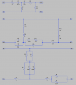
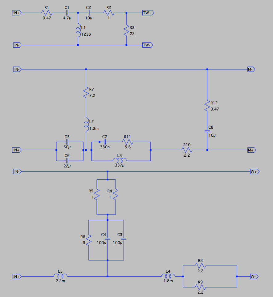
Attached the schematic that I drew. Please check if it makes sense. I have rechecked it 100 times, but I might not see my mistakes.
I don't know the values of inductors so far.
I contacted SEAS hoping to have some specs of the drivers, but they refused.
Woofers are in parallel.
Thanks,
Davide
Attached the schematic that I drew. Please check if it makes sense. I have rechecked it 100 times, but I might not see my mistakes.
I don't know the values of inductors so far.
I contacted SEAS hoping to have some specs of the drivers, but they refused.
Woofers are in parallel.
Thanks,
Davide
Attachments
Last edited:
R1 47 ohms???? did you mean 4.7 ohms? Are those 3 white cement resistors stacked next to the woofer coil?
Looks like all 3 circuits are 3rd order and the woof and mid are wired out of phase with the woof and tweeter in phase.
I presume those are high wattage cement resistors (white ones) next to the woofer coil? Most unusual to see resistors in series with woofers because of the current load in that circuit.
Last edited:
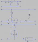
You are right. R1 and R12 are marked R47, so they should be 0.47 ohm. While R3 is marked 22R so it should indeed be 22 ohm.
The three cent resistors are R6. I can read only one that is 15 ohm, so as a first iteration I assumed they have the same value, but I will remeasure when I go to a more intrusive phase.
Woofers are out of phase, while tweeter and mid are in-phase.
Updated schematic attached:
Thanks,
Davide
The three cent resistors are R6. I can read only one that is 15 ohm, so as a first iteration I assumed they have the same value, but I will remeasure when I go to a more intrusive phase.
Woofers are out of phase, while tweeter and mid are in-phase.
Updated schematic attached:
Thanks,
Davide
Attachments
The coils they look indeed a selection from the last three types from here: Coils - Jantzen-audio.com
At what frequency is the inductance quoted and/or measured ?
Thanks,
Davide
At what frequency is the inductance quoted and/or measured ?
Thanks,
Davide
It appears that LP woofer filter part is attenuating too much with its
rather large cored inductor value and the accompanying 200uF's.
Assuming the driver polarities are correct (woofers out of phase),
you could fill the gap by decreasing the L5 value and the same for the
big bypass caps (C3,C4).
My RLC measurement gear automatically measures greater(6mH) inductor
values at about 300 Hz and increases the frequency as the L value lowers.
Free measurement software, ARTA Download does a good job measuring RLC,
although slowly.
Yup, looks like the bass filter is too steep. I fixed the hole with a smaller L5 coil at 2.2mH. Drivers like these.
H1217-08 CA18RLY
H1216-08 CA15RLY
The hole at 1.5kHz is altogether harder to explain. Phase seems right. Maybe the removed dustcap on the mid is the problem?
Altogether a good filter, but the 5R on the bass section, which reduces level 2dB looks a bit wierd. It must get HOT! I'd lose it, and maybe up the mid and tweeter levels to compensate, if it's too bassy. I think you must measure those coils. Multimeters with an inductance scale are invaluable.
Attachments
Good looking schematic. What is that, OrCAD? Haven't seen that in ages. ")
I would suggest you get into using XSim however, as it has built in electroacoustic simulation, will make your exploratons a lot easier and when you start getting your drivers measured, it will make a lot more sense.
Best,
Erik
I would suggest you get into using XSim however, as it has built in electroacoustic simulation, will make your exploratons a lot easier and when you start getting your drivers measured, it will make a lot more sense.
Best,
Erik
You are right. R1 and R12 are marked R47, so they should be 0.47 ohm. While R3 is marked 22R so it should indeed be 22 ohm.
The three cent resistors are R6. I can read only one that is 15 ohm, so as a first iteration I assumed they have the same value, but I will remeasure when I go to a more intrusive phase.
Woofers are out of phase, while tweeter and mid are in-phase.
Updated schematic attached:
Thanks,
Davide
Nikon,
May I suggest, as I often do, OmniMic + DATS V2 as a good investment, or at least DATS to get your drivers measured?
Best,
Erik
May I suggest, as I often do, OmniMic + DATS V2 as a good investment, or at least DATS to get your drivers measured?
Best,
Erik
So I looked up a review of the SF Stradivari Homage, in part because I really like the architectural looks of it. Anyway, it's 3 for three in terms of head scratching response curves from Sonus Faber. Check out Stereophile's detailed breakdown of the lower driver's output (no tweeter here), especially the green and blue traces, whcih are to identical woofers:
An externally hosted image should be here but it was not working when we last tested it.
We seem to be back to the bad filter response:
There's a lot of odd values there, IMO. A lot of of the lump in the bass comes from the reflex tube. Stuffing a sock in it seems a good plan. Still don't like that 5R.
The coils in the mid filter are too small. I don't know what the 15kHz tank notch is meant to do. The tweeter filter is a kinda regular 3-4kHz design for a 4 ohm driver. Lot to think about there, it seems. I think the engineer got fed up with this one, and did some quick and dirty fixes.
Attachments
So I measured the inductances. What's next ?
One cheap experiment that I wanted to try is to listen to them with only ons woofer connected and the other one used as passive radiator. Not sure if it makes sense.
When you meas. the coils, did you disconnect at least one of the two leads from the board?
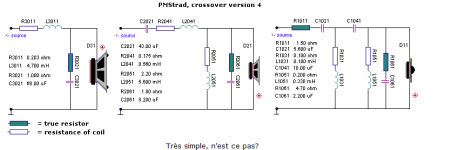
I looked at a design with a 5" SEAS midrange, below diagram:
Poor Man'
Really the trick is to get the midrange on a smooth curve, and build the rest around it. I reckon it wouldn't be hard to fit a MCA15RCY mid, as it goes.
Doubling up the basses is simple enough, halve the coils and resistors, double the capacitor. It seems to work better. With 2X 6" basses, I used 2.2mH and 0.47R and 100uF for the bass filter. The SF mid section is still way off IMO. I think some new bigger coils needed.
Attachments
- Status
- Not open for further replies.
- Home
- Loudspeakers
- Multi-Way
- Sonus Faber Grand Piano Domus