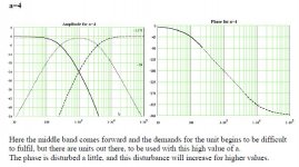
I did a bit of work tonight based on a low order crossover and the published frequency response.
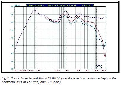
This is a lousy speaker IMO. We must wait and see what the filter actually is, but it looks like it stinks at many levels. Below is my remarkably predictive frequency response. I also tried a proper 3 way filter. A bit inefficient, but how it should be done IMO. Why do people put up with low order crossovers? They just plain distort on complex program material as Lynn often says.
Steve your work on my original B&W Matrix 3's was nothing short of spectacular. If I were the OP here I would be all ears towards Portsmouth. Of course Mr. Bowers did not have the computers and sw we have now, but your crossover design on my units was ideal.
Last edited:
AW, Pete, that was SUCH an interesting thread on the B&W Matrix 3:
http://www.diyaudio.com/forums/multi-way/236806-could-kind-soul-please-break-down-horrid-xover.html
What a nightmare filter, complete with protection circuit! It broke down to something MUCH simpler. That Zaph-type phase/time alignment network on the tweeter turned out to work better as a regular fourth order circuit with polarity flipped. Yet to this day, people still waste time on it!
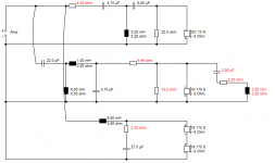
Here's the unrefined circuit I knocked up for the Sonus Faber Grand Piano Domus. It's all regular stuff, including the 6kHz LCR notch on the 6" bass, which is just a good way of taming the near 5kHz cone resonances that ALL 6" basses have. It's actually quite easy to use a big midrange in a 3 way, because you can do some impedance correction on the efficient mid.
So nothing hard about guessing what Troels has done here with the 6" SB acoustics LCR notch and probably 1.5mH bass coil:
SBAcoustics-61-MFC
http://www.diyaudio.com/forums/multi-way/236806-could-kind-soul-please-break-down-horrid-xover.html
What a nightmare filter, complete with protection circuit! It broke down to something MUCH simpler. That Zaph-type phase/time alignment network on the tweeter turned out to work better as a regular fourth order circuit with polarity flipped. Yet to this day, people still waste time on it!
Here's the unrefined circuit I knocked up for the Sonus Faber Grand Piano Domus. It's all regular stuff, including the 6kHz LCR notch on the 6" bass, which is just a good way of taming the near 5kHz cone resonances that ALL 6" basses have. It's actually quite easy to use a big midrange in a 3 way, because you can do some impedance correction on the efficient mid.
So nothing hard about guessing what Troels has done here with the 6" SB acoustics LCR notch and probably 1.5mH bass coil:
SBAcoustics-61-MFC
Attachments
SF Concerto Grand Piano isn't exactly SF Grand Piano Domus.
Although, you're right that CGP has room for electrical improvements,
the beauty of the SF cabinets is almost unsurpassing. Italian school
of design.
If I could go off topic a bit, in my previous work life, I was a tech service engineer for the largest tea bag paper producer in the world and thus gained access to see quite a few tea packing plants around the world.
In one case, I was able to see two completely different designs accomplish the same end result: a tea bag that is folded and stapled (some of you know it as a Lipton tea bag). A German designed machine (Constanta) was quite complex with many moving parts and levers to fold the paper, introduce the tea, fold and staple the bag with a string and paper tag. OTOH, the Italian machine (IMA) probably had 10% of the moving parts the German machine had. Yes, the Italian school of elegant design.,
TBH, I'd leave appearances to the Italians, but engineering to the Germans. Maybe the whole project to the English, who have always gone for the final practical test.
Sorry, but that's how it is.
Engineering is a trade-off. All very well to make the best machine gun in the world, https://en.wikipedia.org/wiki/MG_42. But cheap and cheerful and mass produced has its upside.
The Sten Gun was a terrible design by comparison. You certainly didn't want that accidentally going off within the confines of a US Sherman Tank, which with its Petrol fuel was always a bit of an ignition hazard.
But for sure, easily repaired in the battlefield. Better than waiting months for spare parts.
Whatever I think of the Triumph TR7 and Jaguar XKS cars, the primary consideration was to pull birds. Admit it.Ugh...I have owned a Tr7 and an xks. ☺
Hardly my pure view of engineering. Which is pure science in the end.
The worst problem we have in engineering is that people seek cheap solutions. Hence this compromised Sonus Faber design, which, IMO, doesn't win a cigar at all.
Dear All,
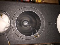
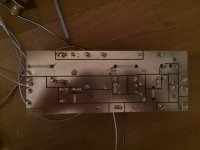
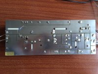
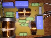
Let's try to fix this: I have done some homework and disassembled the speaker. I am drawing the schematic of the Xover.
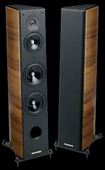
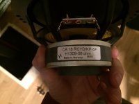
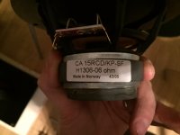
The driver are like in the picture. It's interesting that the midrange has its own enclosure. The woofers are in parallel.
Attached some pictures:
Let's try to fix this: I have done some homework and disassembled the speaker. I am drawing the schematic of the Xover.
The driver are like in the picture. It's interesting that the midrange has its own enclosure. The woofers are in parallel.
Attached some pictures:
Attachments
Not unless the chicks were mechanics😀Whatever I think of the Triumph TR7 and Jaguar XKS cars, the primary consideration was to pull birds. Admit it.
Hardly my pure view of engineering. Which is pure science in the end.
The worst problem we have in engineering is that people seek cheap solutions. Hence this compromised Sonus Faber design, which, IMO, doesn't win a cigar at all.
Very interesting!
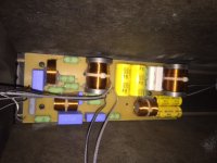
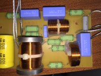
The crossover also looks interesting. Jantzen air and p-core inductors, but less expensive caps.
Lots and lots of caps and resistors in this crossover, I can't wait to see what it finally ends up looking like!
I still wonder if the entire XO design wasn't meant for different drivers.
The woofers were probably Seas with a Scanspeak tweeter? Hmmmm.
Best,
Erik
Dear All,
Let's try to fix this: I have done some homework and disassembled the speaker. I am drawing the schematic of the Xover.
The driver are like in the picture. It's interesting that the midrange has its own enclosure. The woofers are in parallel.
Attached some pictures:
The English (upon which Australian industrial and technological attitudes are traditionally based,) automotive industry reminds me of a consortium of the best DIYers doing what they love and offering their product to the public to keep the wheels turning, kudos to that. But I ride a German bikeTBH, I'd leave appearances to the Italians, but engineering to the Germans. Maybe the whole project to the English, who have always gone for the final practical test.
I ride a Honda, but I always help out those BMW guys on the road.The English (upon which Australian industrial and technological attitudes are traditionally based,) automotive industry reminds me of a consortium of the best DIYers doing what they love and offering their product to the public to keep the wheels turning, kudos to that. But I ride a German bike
Dear All,
Let's try to fix this: I have done some homework and disassembled the speaker. I am drawing the schematic of the Xover.
The driver are like in the picture. It's interesting that the midrange has its own enclosure. The woofers are in parallel.
Attached some pictures:
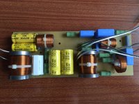
Clearly we must upgrade our impression of Sonus Faber crossovers:

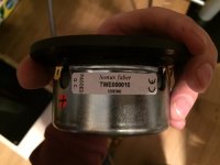
This is not some Mickey Mouse first order jobbie. The 6" SEAS paper bass drivers, 5" SEAS paper midrange and vifa/scanspeak ring radiator tweeter speak of the sort of quality we might expect from a £4,000 loudspeaker.
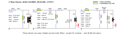
It's always quite hard to disassemble a 3 way crossover. I'd guess the top right is the bass section. The best help I can give you is that this must resemble the three way classic:
SEAS-3-Way-Classic
I'd be looking for something like below.
Attachments
Already there. I've always been enamoured at their RL high pass technique and used it for a few years. With a transformer coupled amp and sub-Watt tweeters I keep it in my arsenal of options.Clearly we must upgrade our impression of Sonus Faber crossovers:
Smart-ar$eI ride a Honda, but I always help out those BMW guys on the road.
In 0.25Mkm I've not had so much as a peep out of my drive shaft, but then I was a mechanic in a former life. I blame the owner if they've never opened a jar of moly grease Attached some pictures:
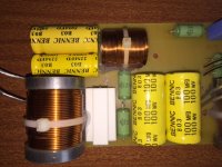
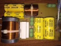
Try to take a better shot of the boards, from both of the
sides, so one can read the values without a problem. Check
the photos before you upload.
...Maybe the whole project to the English...
Sorry, but that's how it is.
If we leave it to the English, then this English better not be
the one that fancies only 2 ways (8" woofer+cone tweeter)
with no measurements, just Visaton database to work with.
Sorry, that's how it is!

Here are more detailed pictures. There are values on the resistors and capacitors, but I do not see and mark on the inductors. I could pull them out and measure DCR and L, but at what frequency do you measure L ?
Attachments
Here are more detailed pictures. There are values on the resistors and capacitors, but I do not see and mark on the inductors. I could pull them out and measure DCR and L, but at what frequency do you measure L ?
Unless you want to go boutique (i.e. $$$$), those blue, PP film caps should be fine as is. Test a few NPE's for uF and ESR to see if in spec. I suspect they will be because Bennic is a good cap maker, at least in my book.
- Status
- Not open for further replies.
- Home
- Loudspeakers
- Multi-Way
- Sonus Faber Grand Piano Domus