Hey all, been messing around in two simulators (and reading as much as I can) for a bit and feel I'm at a point I can ask for assistance since I've run out of ideas/knowledge. Drivers have their depth differences entered in, measured as best as I could.
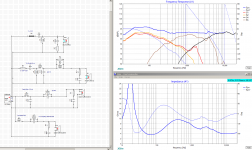
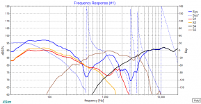
This graph doesn't include baffle losses (from eyeballing edge I'm up 1-1.5db from 100-230hz, and down .5 at 400) or my box tuning/impedance, but I'm hoping it transfers well.
I'm going to try and attach the Speaker Workshop file, as well as the edge.txt. If anyone would be willing to use Blender on the frd provided by Dayton I'd be VERY grateful. I can't get the xls files to work in Open Office.
The reverse nulls are ugly, I can clean up the mid to tweet null a great deal, but at the price of having the peaking midrange being more pronounced. I have the caps and inductors to try both ways. I've read imaging and phase issues can come from a poor null, sometimes.
Also worth a note, the phase plots for the Mid and Tweeter are generated by Xsim/Speaker Workshop. It seems to be fairly accurate when it comes to the Woofers, which have phase provided. It's magic to me so I couldn't make a guess at this point.
If this two woofer deal ends up being a pipe dream, I'll give up and do a standard BSC configuration and use the extra drivers for another build (anyone want to buy two dusty drivers in 2-3 years?)")
Thanks in advance!
The zip (if it uploads) has Xsim, speaker workshop, and driver data files.
This graph doesn't include baffle losses (from eyeballing edge I'm up 1-1.5db from 100-230hz, and down .5 at 400) or my box tuning/impedance, but I'm hoping it transfers well.
I'm going to try and attach the Speaker Workshop file, as well as the edge.txt. If anyone would be willing to use Blender on the frd provided by Dayton I'd be VERY grateful. I can't get the xls files to work in Open Office.
The reverse nulls are ugly, I can clean up the mid to tweet null a great deal, but at the price of having the peaking midrange being more pronounced. I have the caps and inductors to try both ways. I've read imaging and phase issues can come from a poor null, sometimes.
Also worth a note, the phase plots for the Mid and Tweeter are generated by Xsim/Speaker Workshop. It seems to be fairly accurate when it comes to the Woofers, which have phase provided. It's magic to me so I couldn't make a guess at this point.
If this two woofer deal ends up being a pipe dream, I'll give up and do a standard BSC configuration and use the extra drivers for another build (anyone want to buy two dusty drivers in 2-3 years?)
Thanks in advance!
The zip (if it uploads) has Xsim, speaker workshop, and driver data files.
Attachments
Last edited:
I see some problems in what you did. I'll point them in no particular order.
In-box. For crossover simulations you need the real FR from the drivers placed on the intended baffle/box. You do this by building the intended box and measuring with a calibrated mic the FR - or - by taking the published FR and modify it in order to calculate the effect of the baffle/box. For the latter you can use some of the J. Bagby excel tools.
Phase. In order to do crossover simulation your FR (and impedance) data need to have phase info. That phase is minimum phase, and need to be calculated onto the in-box FR, and not onto the plain infinite-baffle FR that many vendors provide (see above). Some of the J. Bagby excel tools can generate phase info.
Blender. You can also do a blend by hand, but if you want to automate the process, as you found out, this useful tool needs excel. Given also the above points, IMHO if someone want to use free software for crossover work, an excel license is somewhat mandatory. I was able to use a PC with Windows 7 and buy a legitimate license + dvd for Office 2003 Basic (only excel + word IIRC) for 25 Euro (money well spent).
x.5 way. I think you are trying to build a 3.5 way, but this is not the correct way to do it. One of the woofer should roll-off early than the other and only the second woofer should cross over to the mid. If both woofers will cross to the mid then simply put the woofers in parallel (or in series). Given your chosen crossover point between woofers and mid I probably wouldn't use a x.5 crossover. Anyway see here how to do the x.5 part: Zaph|Audio - ZDT3.5
Driver depth difference. I don't know what you did so I'll explain the correct method. Using the tweeter axis as listening axis, the sound radiates from the tweeter from a point (x=0, y=0, z=0), and the z axis is toward the listener. The mid and woofer are placed on different x and y, and the sound from them will be generated on a z different from 0 (behind the baffle, for example for a 6.5" driver some 20 mm). If you use PCD you simply insert the (x, y, z) for the mid and woofer and the tool will calculate for you the path difference. If you use SW or XSim, you need to manually calculate that path difference between (0, 0, listening distance) and (x, y, -z), for the 6.5" driver above the difference will be greater than 20mm, approaching 20mm only if the listening distance is infinite.
In general despite the high component count in the crossover you didn't suppress the woofer and mid breakups. You need to do better in that area. Also it seems you placed Zobels on every driver, and this is mainly not necessary anymore.
Ralf
I like that extra bass you've got going on. Looks like that peak on the 6FE100 is a pain even with a high order crossover. Why not just filter the Daytons both the same way without that extra HF output?
If you don't already have the drivers, you may want to consider the tangband w5-704D, it might be perfect as a mid range with those other drivers. It has a really smooth roll off. It's a super value too.
If you don't already have the drivers, you may want to consider the tangband w5-704D, it might be perfect as a mid range with those other drivers. It has a really smooth roll off. It's a super value too.
Giralfino is spot on with his recommendations, though I don't know Blender.
The best way to get accurate measures of the baffle step and driver impedance is with the driver in place. The same thing is true for the driver distance, BUT we can estimate it a little.
For the mid to tweeter, use the difference between the back of the tweeter faceplate to the back of the mid magnet.
Estimate the tweeter/woofer distance the same way, BUT add the tweeter/midrange difference. This is very very rough, but a good exercise in seeing how your phase will change, and why it's not practical to design your crossover until you know these values. I know a thousand people will complain about this, but I will ignore them and remind them that I said this was very rough and not good for actual crossover design.
In your schematic use the "Ground" component to replace all the wires going to the (-) amp terminal. Don't forget to add one to the amp itself as well as all the drivers.
Put padding resistors close to the driver. This will reduce the component values needed, which can add up with expensive caps and inductors. The notch filters can remain between the padding and driver though.
It's easier to match slopes if your combined electrical and acoustical filter orders add up. For instance, if your tweeter is 18db/Octave after the crossover, that's 3rd order. 3 x 90 degrees = 270. 0 degrees + 270 = 270 degrees.
That would require a matching 1st order low pass on the midrange. 1 X 90 = 90. Subtract the phase angle for a low pass ( I may have this reversed, doesn't matter so long as you are consistent). 0 degrees - 90 = 270 degrees.
Remember also that what matters is the combined slope of the driver + crossover.
This is where your designs should start, but at the end of the day, matching phase and amplitude is more important than matching ideal slopes.
XSim trick!
You can use an ideal driver, with an ideal crossover to get a desired graph. Then you can match your driver to it.
For instance, if you want your tweeter to end up with a 2nd order high pass, add an ideal driver in XSim. Add a Circuit Block and set the Hz and Q = 0.7. Move the level to match your tweeter. Now the output of this driver is your goal. Makes it easier to see how close or how far you are from a particular slope and knee.
Thank you for the much appreciated help Ralf and Erik. I've spent several hours re-measuring drivers (and calculating -Z) and messing with simming the needed changes based on your recommendations. I know the -Z and actual FR is likely out. If this sim proves excessively inaccurate I'll purchase a calibrated mic and Excel.
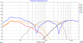
I'm having quite an issue with my mid choice's breakup as Ryan pointed out, and at some point may ditch it for a better suited driver. I may try a lower M-T XOver, though the interwebs say this tweeter has distortion issues.
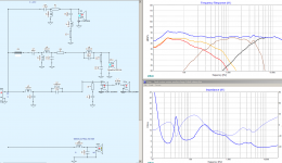
I edited the impedance curves to match what WinISD sims my impedance based on my enclosures to likely be.
As it stands W-M is a LR2 acoustic for both (woofer drops a bit steeper after 20db down.) Mid low pass is LR4 acoustic and tweet is LR2 (well, slightly less but I can't seem to get it steeper without a higher order.)
Do I need to make the tweeter 4th order as well for better phase matching?
Also, I can remove the mid Zobel with a minor inductor tweak. I may do this since it also removes the impedance dip at crossover and phase ripple.
Again, thank you, and if I'm continuing to mess up in some way, please feel free to clue me in.
I'm having quite an issue with my mid choice's breakup as Ryan pointed out, and at some point may ditch it for a better suited driver. I may try a lower M-T XOver, though the interwebs say this tweeter has distortion issues.
I edited the impedance curves to match what WinISD sims my impedance based on my enclosures to likely be.
As it stands W-M is a LR2 acoustic for both (woofer drops a bit steeper after 20db down.) Mid low pass is LR4 acoustic and tweet is LR2 (well, slightly less but I can't seem to get it steeper without a higher order.)
Do I need to make the tweeter 4th order as well for better phase matching?
Also, I can remove the mid Zobel with a minor inductor tweak. I may do this since it also removes the impedance dip at crossover and phase ripple.
Again, thank you, and if I'm continuing to mess up in some way, please feel free to clue me in.
Attachments
Thank you for the much appreciated help Ralf and Erik. I've spent several hours re-measuring drivers (and calculating -Z) and messing with simming the needed changes based on your recommendations. I know the -Z and actual FR is likely out. If this sim proves excessively inaccurate I'll purchase a calibrated mic and Excel.
You don't need a calibrated mic for interferometry. Any non-noisy mic will do. So long as:
- You don't move the microphone, at all during measurements
- You measure the drivers and combined driver outputs with the same microphone.
- Of course, you measure the drivers without a crossover (or no more than a big cap (20uF) on the tweeter)
I'm having quite an issue with my mid choice's breakup as Ryan pointed out, and at some point may ditch it for a better suited driver. I may try a lower M-T XOver, though the interwebs say this tweeter has distortion issues.
I edited the impedance curves to match what WinISD sims my impedance based on my enclosures to likely be.
As it stands W-M is a LR2 acoustic for both (woofer drops a bit steeper after 20db down.) Mid low pass is LR4 acoustic and tweet is LR2 (well, slightly less but I can't seem to get it steeper without a higher order.)
Do I need to make the tweeter 4th order as well for better phase matching?
Also, I can remove the mid Zobel with a minor inductor tweak. I may do this since it also removes the impedance dip at crossover and phase ripple.
Again, thank you, and if I'm continuing to mess up in some way, please feel free to clue me in.
Zobel's are quite handy, sometimes adding one can help you nudge the phase response around, especially if you tweak the C and R values a little. However, depending on your mid, it may be useless.
Best,
Erik
- Status
- This old topic is closed. If you want to reopen this topic, contact a moderator using the "Report Post" button.