Polars indicate it works quite well, but the Horizontal and Vertical coverage charts are bizarre, low frequency response exceeding a Saturn V rocket launch, perhaps that should be "phase angle", not "dB" on the vertical axis ;^).
Hahahaha, probably closer to the center of a star, actually.
")
Very nice work and great fit of the woofers into the relatively flat sides...
The band pass injection holes you have a quite large and within close proximity to throat. Do you have data showing effect of the holes relative to factory polars on pristine horn?
You can call me Chris...it's okay. The horn sidewalls are flat at the throat end of this horn--not "relatively flat"...put a steel rule on the throat area and you can see how flat they are.
See the referenced thread linked at post #1. I detected no real issues with directivity/polars, harmonics, phase, or anything else that I have measured relative to the Klipsch anechoic chamber data, posted above, back to the unmodified K-402 horn with compression drivers only--from whence the anechoic data was measured.
I only see a very mild increase in second and third harmonics around the crossover point. It's pretty difficult to hear the 3rd harmonic when it's -43 dB (peak at 462 Hz)...and lower than -50 dB everywhere else, relative to -50 dB for the unmodified horn--corner loaded.
[I'm wondering what performance issues that you ran into on your large 2" port example that you mention above.]
I didn't wish to elongate the ports any further along the flat horn wall intersections, as that creates problems, too. I'm crossing at 475 Hz, so the woofer ports are far enough from the throat to exceed the physical dimensions of the K-510 horn, which is good down to about 550 Hz (in terms of holding its polars). I wished to keep the compression ratio down to ~10: note the loudspeaker's LF extension.
Chris
Last edited:
Thanks for the photos and polars.
In other words, it is a conical expansion from the mouth up to the secondary horn break, which transitions to a tractrix curve for the last few inches of the horn.
Polars indicate it works quite well, but the Horizontal and Vertical coverage charts are bizarre, low frequency response exceeding a Saturn V rocket launch, perhaps that should be "phase angle", not "dB" on the vertical axis ;^).
I can take credit for screwing up my own measurements, but not in the two coverage plots above, which I believe was mislabeled as "dB" when it's pretty clear that it's really degrees--but neither is my plot nor my data. I don't see any reason to belittle the plots for that oversight: I'd put the quality of that data up against any that I've seen on this site to date.
The guy that designed the horn says that it isn't conical anywhere, only straight-sided (...he's right...). Check your Beranek or Olson. I try to respect the wishes of the man who did it--Roy D. He knows a lot about the subject. It's not conical. But I'll not argue any further.
Chris
I had an issue on mine with 2in dia holes which were subsequently replaced with smaller equivalent of 36mm holes with seven smaller holes.
This is the only posting that I see that's relevant to this topic. I'm still wondering which performance parameters that you've seen that actually suffer. I'd assume that it will be diffraction effects--FR dips/irregularities on-axis, and harmonics at the relevant frequencies on and off axis--and perhaps, in extreme cases and extreme SPLs...directivity issues.
I've measured nothing like that, except the mild increases in 2nd and 3rd harmonics, which was nothing to talk about.
One of the issues that I have with such small ports is port dynamics (sometimes called "chuffing") at very low frequencies, and perhaps under impulsive conditions--like a kick drum or bass drum--close miked. I haven't detected any of those issues.
One of the things that I've found is that you probably need to low pass your crossover settings at the acoustic low pass point of the woofer ports. In my case, that was right where I designed the crossover - 475 Hz. I found that the high pass of the compression driver needed to be extended downward a bit below 475 Hz to cover the center crossover frequency (not unusual in my experience for even non-multiple entry horns), but I attribute that anomaly to port shaping/rounding on the woofer side of the ports, which I didn't optimize: basically I eyeballed the roundover at each port.
Chris
Last edited:
Chris,The horn sidewalls are flat at the throat end of this horn--not "relatively flat"...put a steel rule on the throat area and you can see how flat they are.
I only see a very mild increase in second and third harmonics around the crossover point. It's pretty difficult to hear the 3rd harmonic when it's -43 dB (peak at 462 Hz)...and lower than -50 dB everywhere else, relative to -50 dB for the unmodified horn--corner loaded.
[I'm wondering what performance issues that you ran into on your large 2" port example that you mention above.]
I had no intention of belittling the data with my pointing out that the phase plot was mis-labled, but it took me a while to realize that it was, hence the wink and attempt at humor.
My questions regarding the expansion were not intended as an argument, only to clarify whether the straight sided sections of the horn extended to the apex. Without your clarifications and photos explaining it is "steel rule flat" in that portion, looking at the commercial photos I could not tell whether it was tractrix initially, transitioning to flat, then (obviously) transitioning to tractrix.
XRK's polar performance issues with the 2" diameter ports were due to the relatively large port size compared to the small tractrix horn (a fraction of the size of your K-402), disrupting a relatively large portion of a rapidly curving area.
As you, and those of us putting mid/woofer ports on flat sided portions of horns have discovered, if they are not too large compared to the horn section they enter, they have little effect on any portion of the response, while the benefits of the virtual single point source are quite substantial.
At what distance and SPL are you referencing the HD figures above?
Art
Last edited:
One metre., 100 dB(c)
Yes, I think many people are trying to find the boundaries of a dark room when it comes to multiple-entry horn design. Port size and location (laterally on the horn walls) is one of those areas that are murky. So are the dynamics at the crossover points--acoustic and electrical--in coordination. And what to look for when it's done poorly.
Humor is okay--when it's not at the expense of the persons not making the humor. Otherwise it tends to invite "piling on" (like it did above). I try to substitute the kind of humor that doesn't do that.
Chris
Last edited:
Chris--that was not my intent, and apologize that it came across as such. It simply looked funny and 350 dB is just something a little weird to think about when you have to pile on that many exponents.
Excellent design, to say the least. How are these larger mouth CD's doing with the highest frequencies?
Excellent design, to say the least. How are these larger mouth CD's doing with the highest frequencies?
This is the only posting that I see that's relevant to this topic. I'm still wondering which performance parameters that you've seen that actually suffer. I'd assume that it will be diffraction effects--FR dips/irregularities on-axis, and harmonics at the relevant frequencies on and off axis--and perhaps, in extreme cases and extreme SPLs...directivity issues.
I've measured nothing like that, except the mild increases in 2nd and 3rd harmonics, which was nothing to talk about.
One of the issues that I have with such small ports is port dynamics (sometimes called "chuffing") at very low frequencies, and perhaps under impulsive conditions--like a kick drum or bass drum--close miked. I haven't detected any of those issues.
One of the things that I've found is that you probably need to low pass your crossover settings at the acoustic low pass point of the woofer ports. In my case, that was right where I designed the crossover - 475 Hz. I found that the high pass of the compression driver needed to be extended downward a bit below 475 Hz to cover the center crossover frequency (not unusual in my experience for even non-multiple entry horns), but I attribute that anomaly to port shaping/rounding on the woofer side of the ports, which I didn't optimize: basically I eyeballed the roundover at each port.
Chris
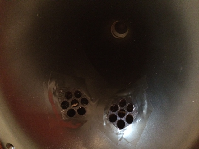
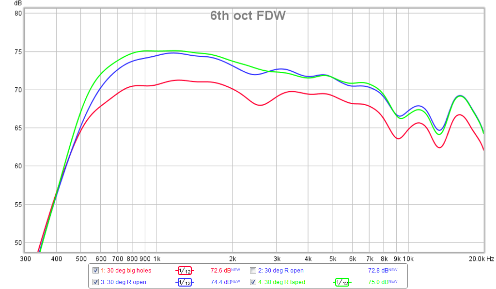
More in the Bookshelf multiway single point source horn thread. Basically, the rather large holes relative to the horn wall surface area caused a 2.5dB reduction in the sound and added dips. I fixed it by installing a 3D printed cover over the compound curved wall shape fitted with seven smaller holes. The fix was measurable and almost restored it to pristine horn wall performance.
Here is data at 30deg off axis - basically beyond the nominal 25deg of this 50deg horn (used in vertical orientation). Red is big holes, blue is the fix, green is holes taped over to simulate pristine horn:
http://www.diyaudio.com/forums/multi-way/285030-bookshelf-multi-way-point-source-horn-74.html
...Basically, the rather large holes relative to the horn wall surface area caused a 2.5dB reduction in the sound and added dips. I fixed it by installing a 3D printed cover over the compound curved wall shape fitted with seven smaller holes. The fix was measurable and almost restored it to pristine horn wall performance.
Thanks for that. I certainly see your point for your MEH design in your thread. I didn't notice that effect at all in this design although I did do a complete EQ of the assembly after attaching the woofers with their off-axis ports, almost entirely associated with the LF bi-amping channel, since the HF compression driver channel significantly rolls off below 400 Hz. I didn't change the EQ on the HF channel except near the crossover point (475 Hz).
This modification basically was like opening a window for LF production to come through for the current horn since the compression driver was the limiting factor in the benign (axial driver only) case.
Chris
Takes some cojones to put holes in your 402s.... Wow..
Hey there seti.
I acquired the KPT-305 mid bass module with these modifications in mind, so...not really. That was the plan. I'll never look back since the result was a dramatic increase in performance, exceeding that of the basic Jubilee performance by a fair margin and finally settling the center channel problem between Jubs--except that now, the Jubs are next in the crosshairs.
You need to stop by for a listen sometime perhaps as a diversion on your next trip to Austin. Hearing is believing.
Chris
In the design represented in the present thread, the crossover point is actually defined by the 1/4 wavelength distance of the off-axis ports to the throat port, not attempting to cross higher than that natural break.
Other than the trying to reduce the size of the horn...as in the "bookshelf Synergy" thread, I see no reason to attempt to cross at a higher frequency, at least not for the current configuration.
Perhaps there should be discussion on how much overlap between the co-axial "ways" of the multiple entry horn design between sets of ports. It seems to me that one of those trade offs should be the sizing of off-axis ports to avoid:
1) port chuffing (a.k.a., compression ratio), but also...
2) time smearing due to port elongation along horn walls toward the mouth--which is a commonly used technique to avoid enlarging the ports laterally around the throat, and...
3) the audible effects of using large bass reflex ports in the horn near the mouth on the time domain performance of the horn, i.e., "group delay growth" toward lower frequencies that those reflex ports bring in terms of their design trade-offs.
Chris
Chris,In the design represented in the present thread, the crossover point is actually defined by the 1/4 wavelength distance of the off-axis ports to the throat port, not attempting to cross higher than that natural break.
Other than the trying to reduce the size of the horn...as in the "bookshelf Synergy" thread, I see no reason to attempt to cross at a higher frequency, at least not for the current configuration.
Perhaps there should be discussion on how much overlap between the co-axial "ways" of the multiple entry horn design between sets of ports. It seems to me that one of those trade offs should be the sizing of off-axis ports to avoid:
1) port chuffing (a.k.a., compression ratio), but also...
2) time smearing due to port elongation along horn walls toward the mouth--which is a commonly used technique to avoid enlarging the ports laterally around the throat, and...
3) the audible effects of using large bass reflex ports in the horn near the mouth on the time domain performance of the horn, i.e., "group delay growth" toward lower frequencies that those reflex ports bring in terms of their design trade-offs.
Chris
If the offset injection port to port distance is (much) over 1/4 wavelength, off axis polar response starts to be compromised with peaks and dips in their upper crossover range. That compromise must be weighed against the reduced distortion afforded by the HF driver not extending as low. Of course, the response of the offset drivers must be considered- if they don't respond smoothly above a certain frequency, that limits how high they can be used without a "hole" in the crossover range. The larger the mid/low driver, the lower the crossover must be, due to the larger volume of the band pass chamber. Larger drivers also generally have more Xmax, which further increases the volume of the band pass chamber even if a volume reducing cone is placed inside.
1)I have not noticed any chuffing from the ports in the SynTripP design, they have a similar ratio of Sd to port area as your horn. Unlike port chuffing in a subwoofer which can easily be identified by a differing location from where you would expect to hear HF noise, any offset port chuffing noise would tend to be masked by the virtual point source of the HF.
2)The path length from various parts of the cone to the port output are all different. The length of the port, as is usual, varying from round to perhaps a 4/1 aspect ratio, is still less than the path length from various parts of the cone, so makes little difference in the time smearing.
3)The time domain performance of a bass-reflex arrangement can be aligned (group delay growth eliminated) using FIR filters, resulting in flat phase response. The reduction in excursion and increased LF output around Fb do reduce distortion by comparison to a sealed alignment. Even though I still have yet to employ FIR filters in the SynTripP, the advantages of the BR ports still outweigh the audibility (pretty much inaudible to me) of the phase shift in the 80 Hz region.
Art
- Status
- This old topic is closed. If you want to reopen this topic, contact a moderator using the "Report Post" button.
- Home
- Loudspeakers
- Multi-Way
- A different horn