I was still typing and generally set the spacing within range of 1/4 wave to 1/2 wave. Sometimes people use single value of 1/3-wave as a goal.
Cool - thought I had used the calculator wrong or something!
PS - Guess what?
Yes, 6.78" C to C would be 1/4 wavelength at 500 Hz. Still requires placement a lot closer to the throat than your red ports indicate if you desire smooth polars in the 500 Hz crossover region.
I didn't realize you were planning to cross the little full ranger so low, should have looked closer before posting.
Art
Don't worry - at that placement they are 6.3 inches C-C - so still within 1/4 wavelength.
The SB65 has a Fs of 115, and a helpful 2.6mm x-max so shouldn't be a prob crossing in the 400-500hz range.
What is the estimated SPL of the SB65 at one meter at 400 Hz (and 500 Hz) driven to Xmax on the horn you are using?Don't worry - at that placement they are 6.3 inches C-C - so still within 1/4 wavelength.
The SB65 has a Fs of 115, and a helpful 2.6mm x-max so shouldn't be a prob crossing in the 400-500hz range.
It's thermally limited rather than xmax limited. Let me run sim to xmax on SB65 but it's probably just a bit higher than the 116dB shown here. It's a rather low sensitivity driver to start with.
Since the IEC 268-5 SB65 20 watt rating uses a 6 dB crest factor pink noise signal (rolled off at 200 Hz 12 dB per octave), I'd think short peaks of +6dB (80 watts) would easily be sustainable. My horn loaded 30 watt TC9 sustained peaks over 800 watts before letting out the magic smoke ;^).It's thermally limited rather than xmax limited. Let me run sim to xmax on SB65 but it's probably just a bit higher than the 116dB shown here. It's a rather low sensitivity driver to start with.
Appreciate your checking.
As an update, my multiple driver TC9 experiments have all had horrific polar response :^(.
Five Maltese horns have been sacrificed so far...
Art
These were polars I was getting on tractrix Trynergy with 3.5in drivers.
Not the prettiest that's for sure. Hopefully the 18Sound WG being a real computer designed horn will fare better.
Not the prettiest that's for sure. Hopefully the 18Sound WG being a real computer designed horn will fare better.
seems like this PRV Audio WG35-25-B 1" 90 x 60 ABS Waveguide 2/3-Bolt would be a better choice for such a project- rather than have to have long vents to accommodate the flare, you can mount right on it. The cost is some effort modifying the throat to size- but we're not afraid of that, are we?

Since the IEC 268-5 SB65 20 watt rating uses a 6 dB crest factor pink noise signal (rolled off at 200 Hz 12 dB per octave), I'd think short peaks of +6dB (80 watts) would easily be sustainable. My horn loaded 30 watt TC9 sustained peaks over 800 watts before letting out the magic smoke ;^).
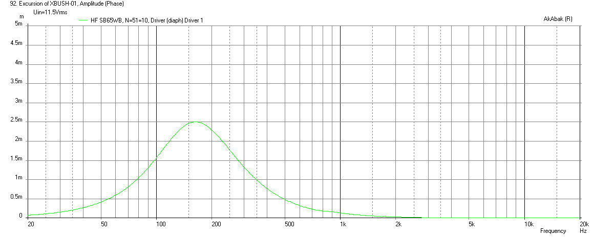
So I will present two cases: (1) the 200Hz -12dB/oct Butterworth high pass filtered SB65WBAC25-4 as used in this 18Sound WG at maximum cone excursion of 2.5mm. (2) with a 350Hz -12dB/oct BW high pass filter as used for the current design which provides an electro-acoustic XO of about 500Hz, pushed to xmax.
Here is predicted cone excursion on SB65 pushed to xmax with 200Hz BW2 filter:
And here is the corresponding electrical power input (about 36 watts rms):

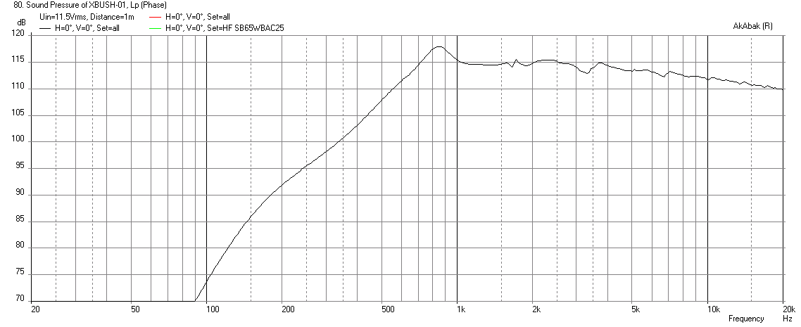
Here is the max SPL output - only about 108dB at 500Hz:
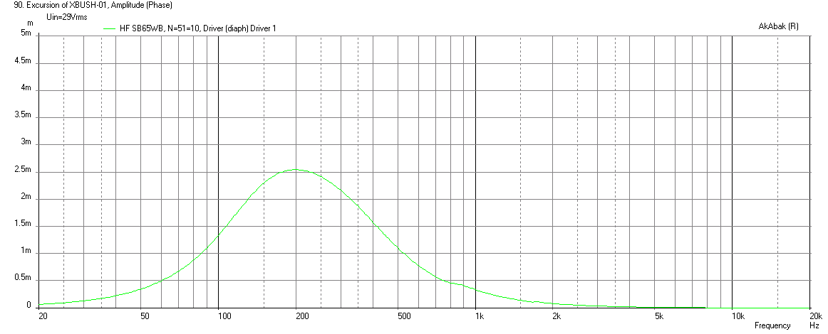
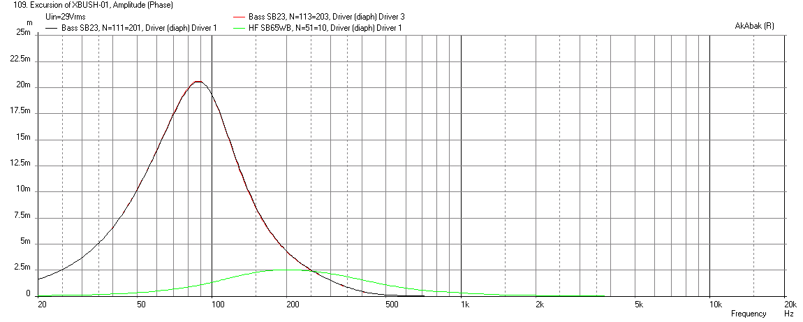
But if we increase the high pass filter to 350Hz BW2, it significantly reduces cone motion and xmax happens at a much higher drive voltage of 29v vs 11.5v:
Here is corresponding electrical power input (about 225 watts):
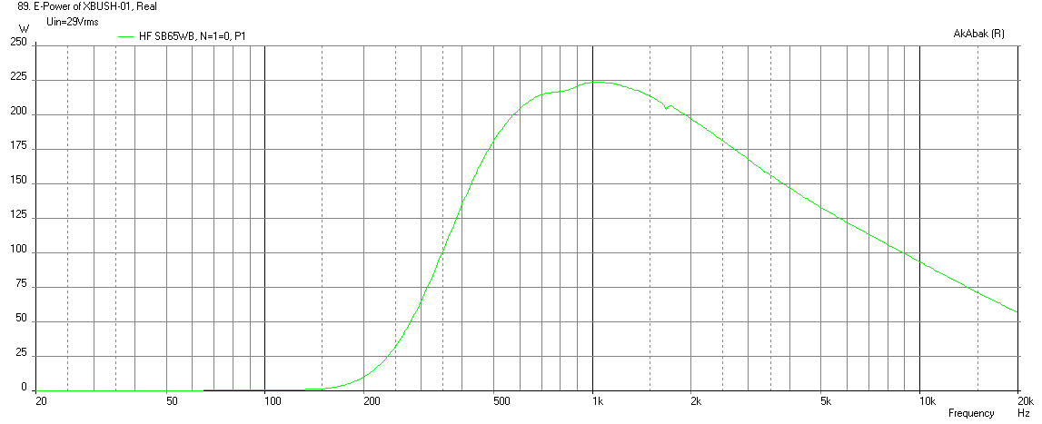
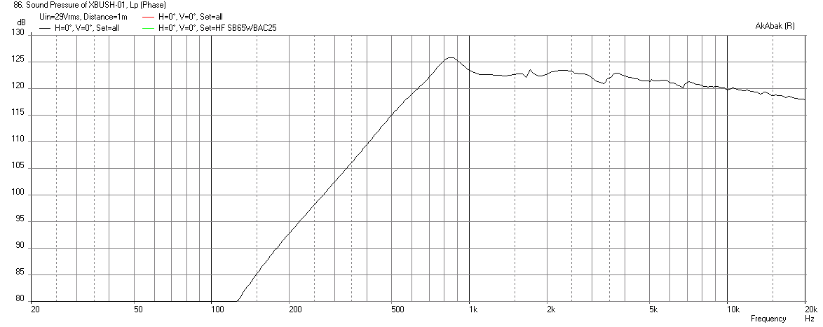
Here is the corresponding xmax limited SPL of the SB65 at this drive level which well exceeds the thermal rating. Probably OK for bursts up to 5 seconds or so? Can get quite loud though - good for 115dB at 500Hz, and 123dB on the main gain profile for the WG but that is on the edge of the waveguide gain profile plus the 350Hz HPF:
Note that these sims are using a very rough 5 point approximation of the 18Sound WG. I could have asked Bushemeister for more points to give better fidelity in modeling the horn but this is close enough for purposes of matching driver levels and figuring out how big to make ports etc.
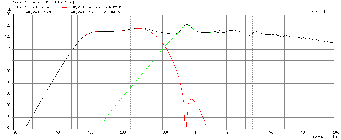
Out of curiosity, I then allowed the woofers to be driven at required voltage to match the SPL of the SB65 and it takes 78.3 volts ( an impossibility with the 8's - would need a pair of pro sound woofers for this application). But the max SPL is about 123dB and about a 2kW of electrical power into those SB23's 🙂
Displacement:
Max SPL:
Max power:

Attachments
-
 Xbush1-SB65WBAC25-4-200Hz-12db-xmax-limit-max-displacement.png11.1 KB · Views: 936
 -
 Xbush1-SB65WBAC25-4-200Hz-12db-xmax-limit-max-electrical-power.png11.2 KB · Views: 926
 -
 Xbush1-SB65WBAC25-4-IEC-200Hz-12db-xmax-limit-max-SPL.png32.2 KB · Views: 930
 -
 Xbush1-SB65WBAC25-4-350Hz-12db-xmax-limit-max-displacement.png11.1 KB · Views: 888
 -
 Xbush1-SB65WBAC25-4-350Hz-12db-xmax-limit-max-Elect-power.png11.3 KB · Views: 889
 -
 Xbush1-SB65WBAC25-4-350Hz-12db-xmax-limit-max-SPL.png12.2 KB · Views: 902
 -
 Xbush1-SB23RNXS45-8-SB65WBAC25-4-350Hz-12db-xmax-limit-max-SPL-78v.png14.7 KB · Views: 898
 -
 Xbush1-SB23RNXS45-8-SB65WBAC25-4-350Hz-12db-xmax-limit-max-displacement.png13.8 KB · Views: 892
 -
 Xbush1-SB23RNXS45-8-SB65WBAC25-4-350Hz-12db-xmax-limit-max-electrical-power-78v.png11.3 KB · Views: 886
Last edited:
seems like this PRV Audio WG35-25-B 1" 90 x 60 ABS Waveguide 2/3-Bolt would be a better choice for such a project- rather than have to have long vents to accommodate the flare, you can mount right on it. The cost is some effort modifying the throat to size- but we're not afraid of that, are we?
A 1-inch throat won't work well with a 2.5in dia full range cone. Maybe with a conventional compression driver but then we are just back to a standard synergy/unity with ports stuffed up as close as possible to throat with a 1.2k XO and correspondingly higher levels of HD that a compression driver has vs a cone driver in a WG.
Xrk - have you missed my measurements? What do you think?
Yah, I did - was deep in sim land pushing this horn to its extremes. Just looking at it now. Will get back to you... thanks for heads up. 🙂
I thought laptop wasn't coming back until tomorrow or possibly Monday? Good news though.
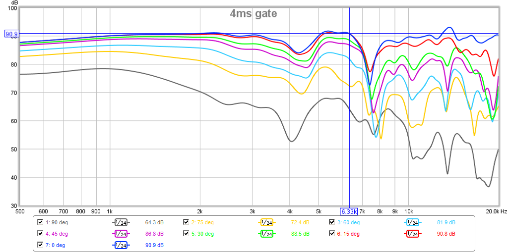
The polars are show uniform power that falls off evenly over range and nothing wierd.
You did an excellent job on keeping things smooth around throat and it shows - the horn response is smooth from bottom to first cancellation dip at 5.7k. 5.7kHz corresponds to a 30mm distance from something to the throat, or edge of surround to center of throat. 54mm throat + 6mm is indeed 30mm radius to center. So I think that is cancellation of reflection from rubber surround to center. Nothing you can do about except maybe print a 3d phase plug but that adds other issues.
So, I think this looks like a promising WG - GREAT in fact! 🙂
The predicted peak at circa 800Hz matches what Akabak model says, the fall off is what I expected. The first cancellation dip is at 5.7kHz which is not bad - and the extension goes up to 20kHz. This can be easily compensated with either a high shelf filter at 1kHz to flatten the response. And from the sims, there is plenty of xmax here to work with - just have to watch thermal peaks if playing sustained higher SPL's. The 5.7k notch is narrow you won't hear it and it is just at top of telephone band so leave it alone.
You can also do a high pass filter, maybe -12dB/oct at 6kHz and that will push gain of SB65 down to match woofers around 500Hz XO, and then add a little high shelf as needed to flatten response. I think no more than 3 broad PEQ's should flatten this out nicely.
Nice work!

Last edited:

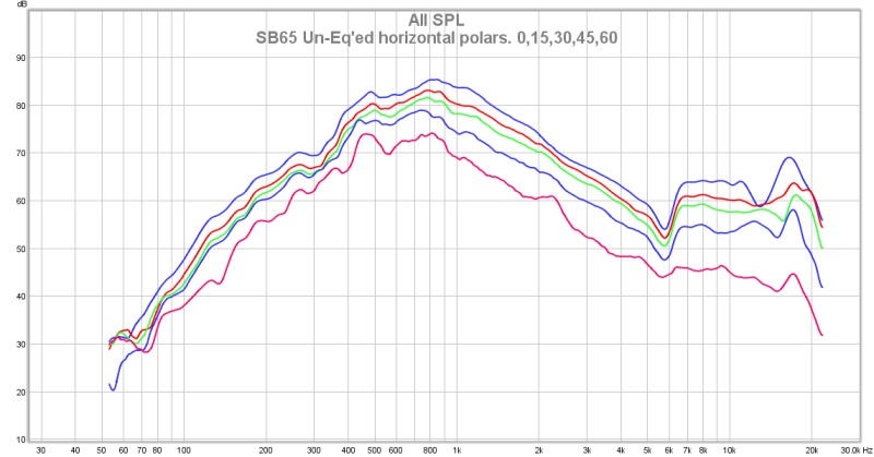
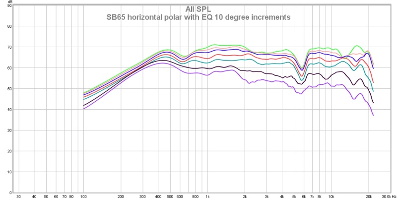
OK - Xrk - here you go, some quick and dirty measurements gated to 5ms. 10 degree increments after some EQing...
As you predicted the diffraction is present just below 6000hz
This is even better than I expected 🙂
Wow! I got to get me some XT WG's...
That looks very nice indeed. I don't think some slots/holes are going to mess it up too much.
How does it sound?
One trick that Bruce Edgar used on his tractrix horns to help reduce that first cancellation dip was to put a ring of scotchbrite or reticulated open cell foam between the driver bezel and the horn flange. He made the depth (width of foam ring equal to 1/4-wave Helmholtz resonator frequency) equal to a 1/4-wave tuning-stub to help absorb some of that dip. In this case, the half-wave was 30mm, so a 15mm deep foam or scotchbrite gasket stub may help to flatten the response there. I have not tried it and it may not work and be finicky to density of foam or whatever. But something to think about as a purely passive way to reduce that dip.
In practice, I don't think you will hear that dip - so maybe fine. Dips are not audible like peaks of same magnitude. Generally a no-no to fill a dip as that adds HD but possibly try a small +5dB Q=1.3 PEQ at dip frequency to make it less noticeable. That won't add too much HD and may smooth out phase somewhat to benefit. Don't apply +10dB peak PEQ in any circumstance though.
Last edited:
OK - Xrk - here you go, some quick and dirty measurements gated to 5ms. 10 degree increments after some EQing...
As you predicted the diffraction is present just below 6000hz
: ) thanks sharing.
After advise by wesayso and a guide another thread if you have REW installed in version 5.13 or 5.14 could you show same overlay plot but with gate back to default 500mS and then frq dependent window as below and then hit "Apply Windows to All".
Attachments

I - don't seem to have that option in my REW- I bet mine is out of date - I will try an update.
I can't believe I am still running v5.01 Beta 17 Build 2967 🙂 I will upgrade as well...
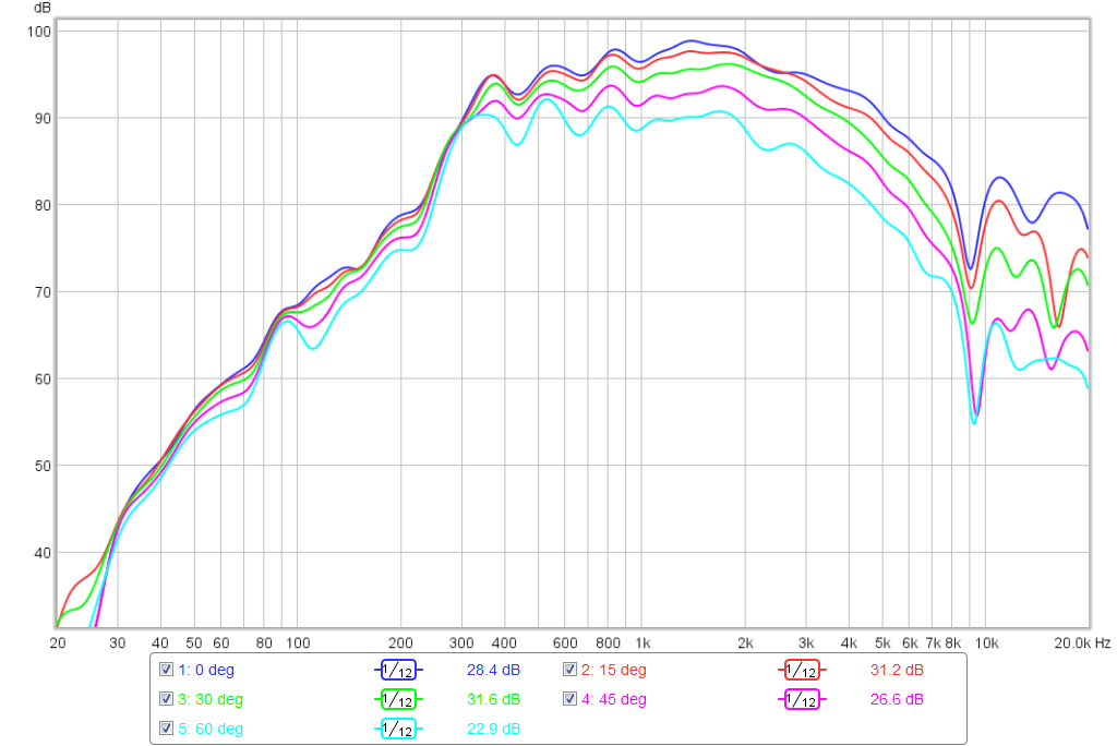
Well that was truly painless - took 3 minutes. Here are polars of my W2-852SH in uTrynergy tractrix with 1/6th octave frequency dependent window at 0 deg to 60 deg in 15 deg increments:
Ok, I don't what I am doing here but if I set to 5ms gate and 1/6th oct freq dependent window smoothing I get this:
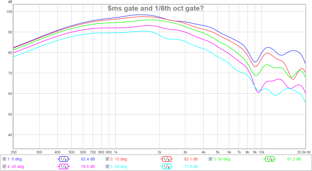
Can you do both and what does it mean?
Here is corresponding phase for above:

Well that was truly painless - took 3 minutes. Here are polars of my W2-852SH in uTrynergy tractrix with 1/6th octave frequency dependent window at 0 deg to 60 deg in 15 deg increments:
Ok, I don't what I am doing here but if I set to 5ms gate and 1/6th oct freq dependent window smoothing I get this:
Can you do both and what does it mean?
Here is corresponding phase for above:
Attachments


Last edited:
: ) thanks sharing.
After advise by wesayso and a guide another thread if you have REW installed in version 5.13 or 5.14 could you show same overlay plot but with gate back to default 500mS and then frq dependent window as below and then hit "Apply Windows to All".
I was just about to mention that. I would also love to see a frequency + phase plot with that same frequency dependant filter set. The dip is acting the same over all angles, lets see what phase does there.

- Home
- Loudspeakers
- Multi-Way
- A Bookshelf Multi-Way Point-Source Horn