.....Love your recent STEP plots though 😀. Is this at listening distance?
Year IR and SR is finest data i ever had and also SQ is best i had but unfortunate distance is usual near field stuff, did a APL_TDA sweep last weekend at 2,5 meter distance and did not find any need to save as file
 . Look forward learning from upcoming exercise, thank you for the offer and thanks to bushmeister taking the challenge.
did a APL_TDA sweep last weekend at 2,5 meter distance and did not find any need to save as file
May i ask why? It was ugly?
Summary pics.
Attachments
-
 Xbush1-SB65WBAC25-4-350Hz-12db-xmax-limit-max-SPL.png12.2 KB · Views: 2,604
 -
 IMG_20160112_224346.jpg252.2 KB · Views: 2,508
 -
 IMG_20160112_224132.jpg356.1 KB · Views: 2,485
 -
 IMG_20160109_105124.jpg260.9 KB · Views: 2,718
 -
 Xbush-01-sb23nrxs45-8-SPL-Displacement-at-2.83v-50mm-12mm-thick-65Hz-HPF.png13.2 KB · Views: 2,468
 -
 Xbush-01-sb23nrxs45-8-SPL-Sensitivity-2.83v-50mm-12mm-thick-65Hz-HPF.png13.9 KB · Views: 18,866
 -
 Xbush-01-sb23nrxs45-8-max-SPL-Displ-22.8v-50mm-12mm-thick-65Hz-HPF.png13.3 KB · Views: 2,528
 -
 IMG_20160114_151614.jpg150.3 KB · Views: 2,605
 -
 Xbush1-SB23RNXS45-8-SB65WBAC25-4-350Hz-12db-xmax-limit-max-SPL-78v.png14.7 KB · Views: 2,586
 -
 sb65 mounting.jpg55.9 KB · Views: 6,774
Summary pics 2
Attachments
-
 IMG_20160124_193858.jpg221.5 KB · Views: 2,469
 -
 IMG_20160124_200125.jpg224.2 KB · Views: 2,448
 -
 IMG_20160120_214528.jpg241.7 KB · Views: 19,936
 -
 IMG_20160114_091202.jpg115.6 KB · Views: 2,472
 -
 IMG_20160118_203734 (1).jpg272.9 KB · Views: 2,461
 -
 IMG_20160119_222628.jpg248.6 KB · Views: 2,467
 -
 Ribs ground down.jpg325.3 KB · Views: 2,456
 -
 IMG_20160114_161624.jpg412 KB · Views: 2,451
 -
 Distortion 90dB 350 BW2.jpg83.8 KB · Views: 2,488
 -
 IMG_20160114_122512.jpg231.3 KB · Views: 3,063
Summary pics 3
Attachments
-
 IMG_20160213_153943.jpg219.2 KB · Views: 2,417
 -
 IMG_20160211_183015.jpg236.8 KB · Views: 21,004
 -
 IMG_20160203_194047.jpg556.2 KB · Views: 2,436
 -
 IMG_20160203_072759.jpg265.9 KB · Views: 19,368
 -
 IMG_20160203_072752.jpg338 KB · Views: 2,426
 -
 IMG_20160202_222226 (1).jpg601 KB · Views: 2,437
 -
 IMG_20160202_221040.jpg367.9 KB · Views: 2,436
 -
 IMG_20160202_215132.jpg260.2 KB · Views: 2,442
 -
 IMG_20160131_164416.jpg285.7 KB · Views: 2,687


The X-Bush Speaker.
A 2-way synergy speaker using full range drivers.
Bushmeister.
This is a write up of the build of the X-Bush speaker – a collaborative project mainly between two DIYaudio members – Bushmeister and Xrk971.
This was spawned due to my interest in building a DIY synergy horn using a commercial SOTA CD horn rather than a plywood DIY synergy horn as previous DIY builds had done.
I reasoned that the newer CD horns were designed using Computer Aided Finite Element Analysis to avoid the disadvantages usually associated with traditional diffraction/straight sided horns and therefore if this SOTA technology could be combined with synergy loading techniques, the best of both worlds might be achieved.
I was set to build one using a CD for treble and small mid drivers – in the more usual implementation of synergy horns – probably as a 3-way. Then I spotted xrk971’s experiments with full range horn loaded drivers.
He hadn’t tried a full range driver on a commercial horn, but had experienced promising results on his home cooked foam core horns. The most interesting results were in substantially lower HD than CDs, and the ability to run the full range driver down to 500Hz, allowing a 2-way crossover to a woofer rather than a mid-driver.
I immediately felt this would be a better technique than using a CD for treble – lower HD is always nice, but I was worried placing mid driver taps very close into the horn throat would largely be of detriment to the SOTA horn I was planning on using. A 2-way approach crossed over approx. 500-600 Hz would allow the woofer tap placement nearer the mouth of the horn, and still keep them within ¼ wavelength (important for the synergy design to work).
So after much reading on CD horn designs, I chose the Eighteen Sound elliptical shape technology (ESS), XT1464 constant coverage high frequency horn.
This provided a 60x40 degree pattern control horn down to almost 500Hz horizontally – key ingredients in my design choices. I didn’t want the speaker to be wider than 18” or so, yet I wanted good control to 500Hz as this seemed to be an important minimum CD frequency.
So I ordered the horns.
The next choice was the full range driver to match to the horn. Again, I was largely inspired by the work of Xrk971 – his full range driver threads and horn experiments led me to believe the two best candidates were either the TC9 or the SB65WBAC25.
Given the throat size of the XT1464 (1.4 inches) I knew the TC9 would be too large, so I ordered two SB65WBAC25s.
At this point I was planning on embarking on modelling the drivers on the horn and various injection port sites etc. i.e. doing this all on my own. However, when I mentioned my intentions on DIYaudio Xrk971 immediately offered to help me with the modelling and planning. As he is incredibly talented with software speaker modelling, whilst I enjoy the practical building and engineering challenges, it seemed like a perfect collaborative project (even if we were geographically ~4000 miles from each other).
I promptly measured up the horns so he could model a 3D form and things then began to move very swiftly…..
Xrk quickly discovered the SB65 were greatly assisted by the horn loading, to such a point that despite the 2.5mm X-max they would likely have greater output than the woofers I had initially chosen:
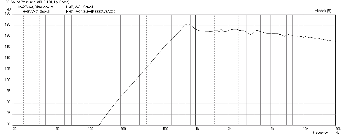
SB65WBAC25-4 -max-SPL
As can be seen the SB65 would run up past 120dB within X-max, and is actually only limited thermally. This led me to look into some more capable woofers for the two way implementation.
I like SB acoustics offerings and their SB23NRXS45-8 8” woofers caught my eye. It seemed to have ideal TS parameters, was very low distortion and had ideal physical dimensions to mount onto the XT1464 neatly.
I ran it past Xrk971, who promptly modelled it at x-max to see if the dual 8” woofers could keep up with the small SB65 horn loaded full range unit:
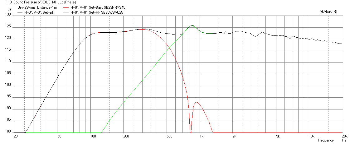
SB23RNXS45-8-SB65WBAC25-4-350Hz-12db-xmax-limit-max-SPL-78v
You can see it is impressive how the tiny SB65 keeps up with the two 8” units.
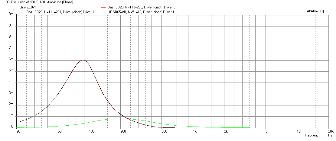
sb23nrxs45-8-max-SPL-Displ- -65Hz-HPF
As can be seen, they were an ideal match – similar max outputs, the SB65 being thermally limited, whilst the SB23 were x-max limited (see excursion plot).
It was also interesting to note how the horn loading had affected sensitivities and how low the excursion was at ‘normal’ sound pressure levels (I believe this is central to the reasons this design has such low HD).
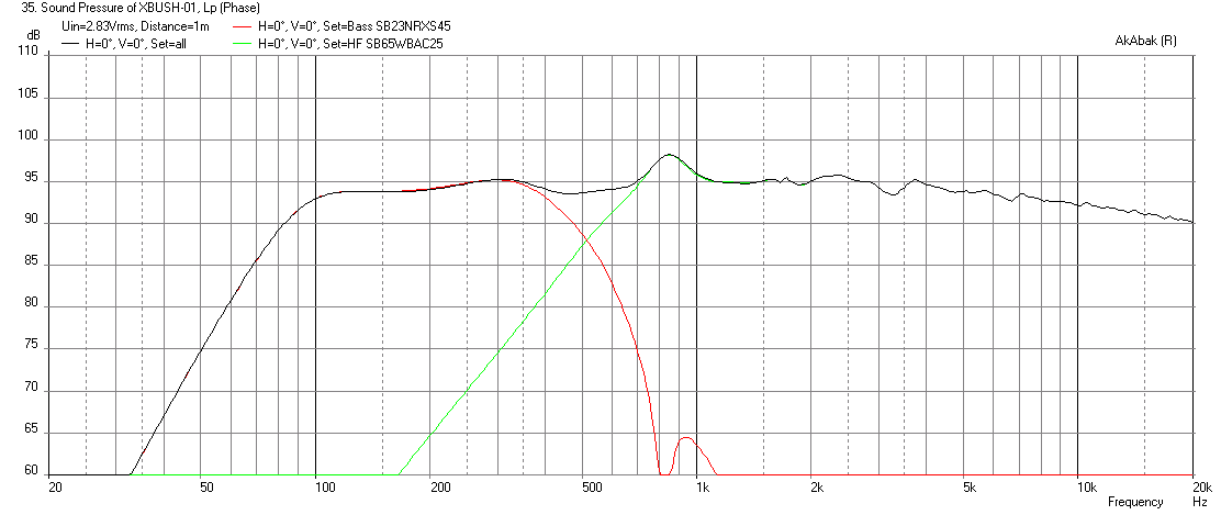
sb23nrxs45-8-SPL-Sensitivity-2.83v-65Hz-HPF
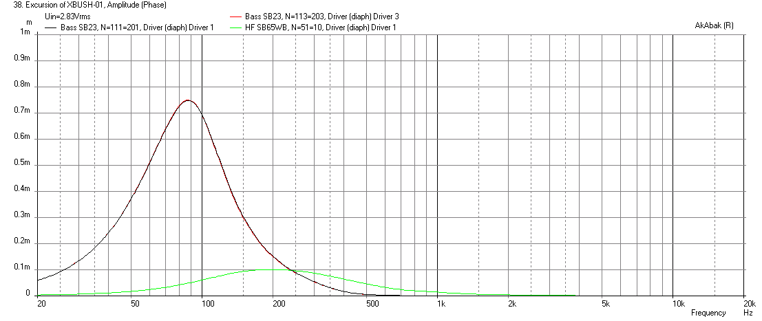
sb23nrxs45-8-SPL-Displacement-at-2.83v- -65Hz-HPF
As you can see at 95dB (the Xbush sensitivity at 2.83v) the woofers are only moving 0.7mm, and the SB65 a mere 0.1mm (100 microns). So no wonder HD is very low.
I then began the engineering task of working out how to put the pieces together to do justice to the sims!
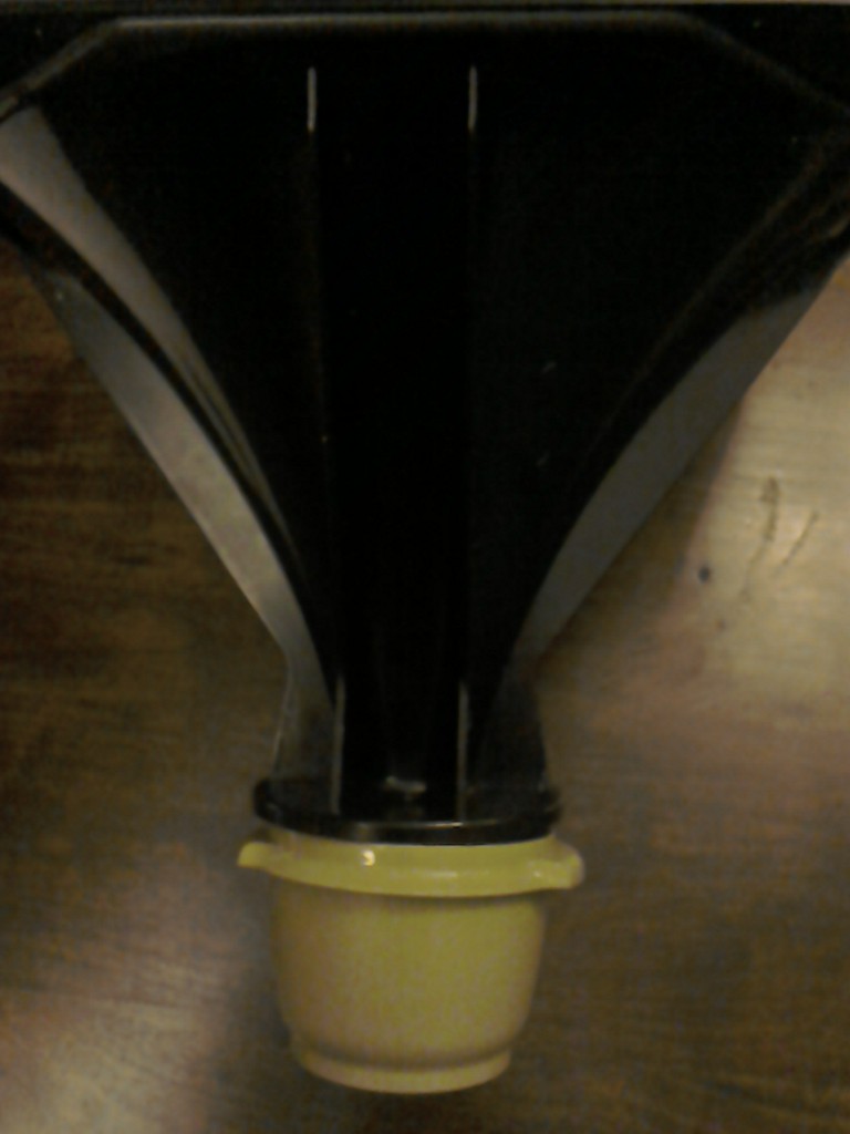
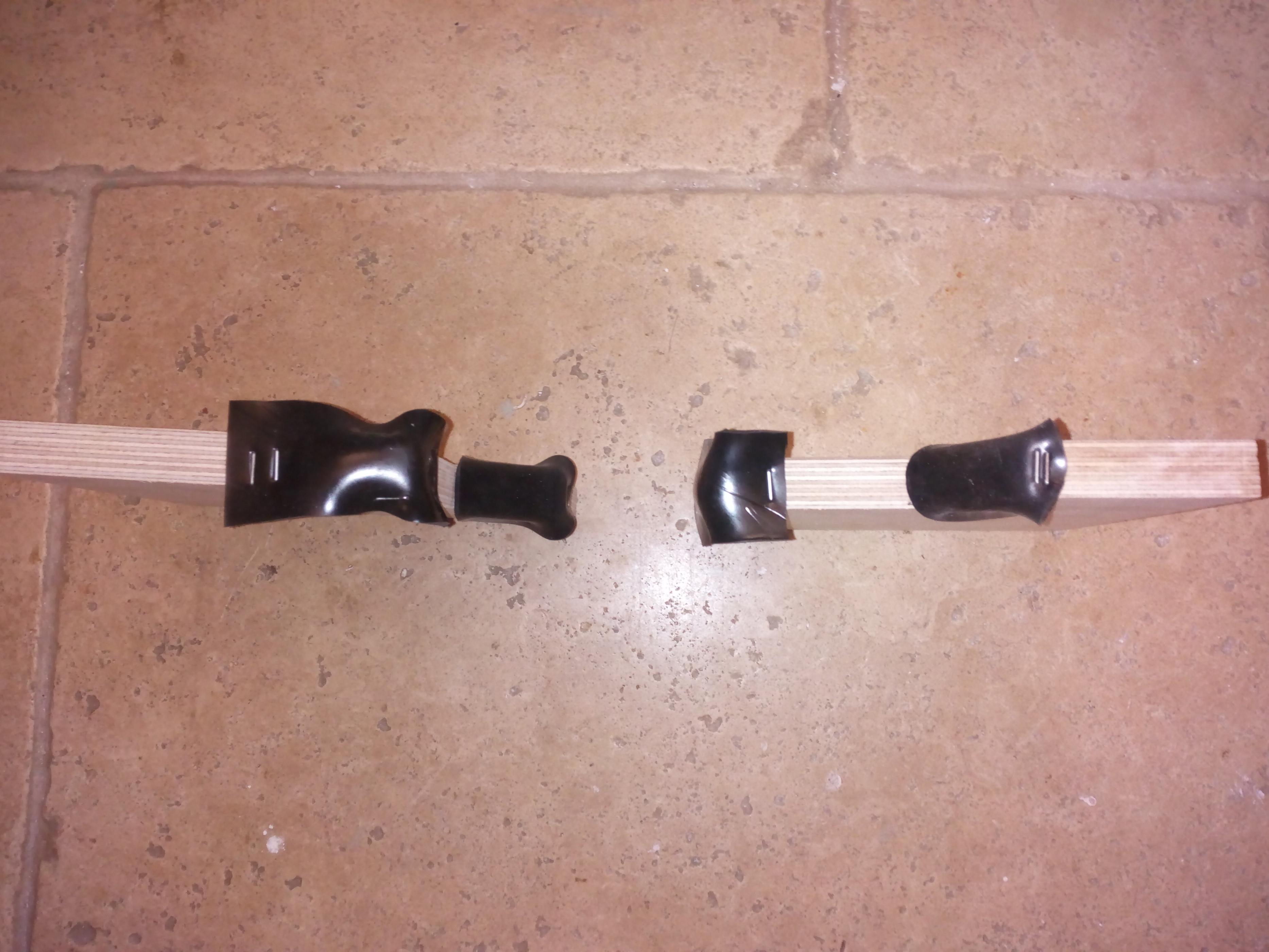
The first problem was mounting a 2.5” full range driver onto a horn designed for a bolt on 1.4” CD.
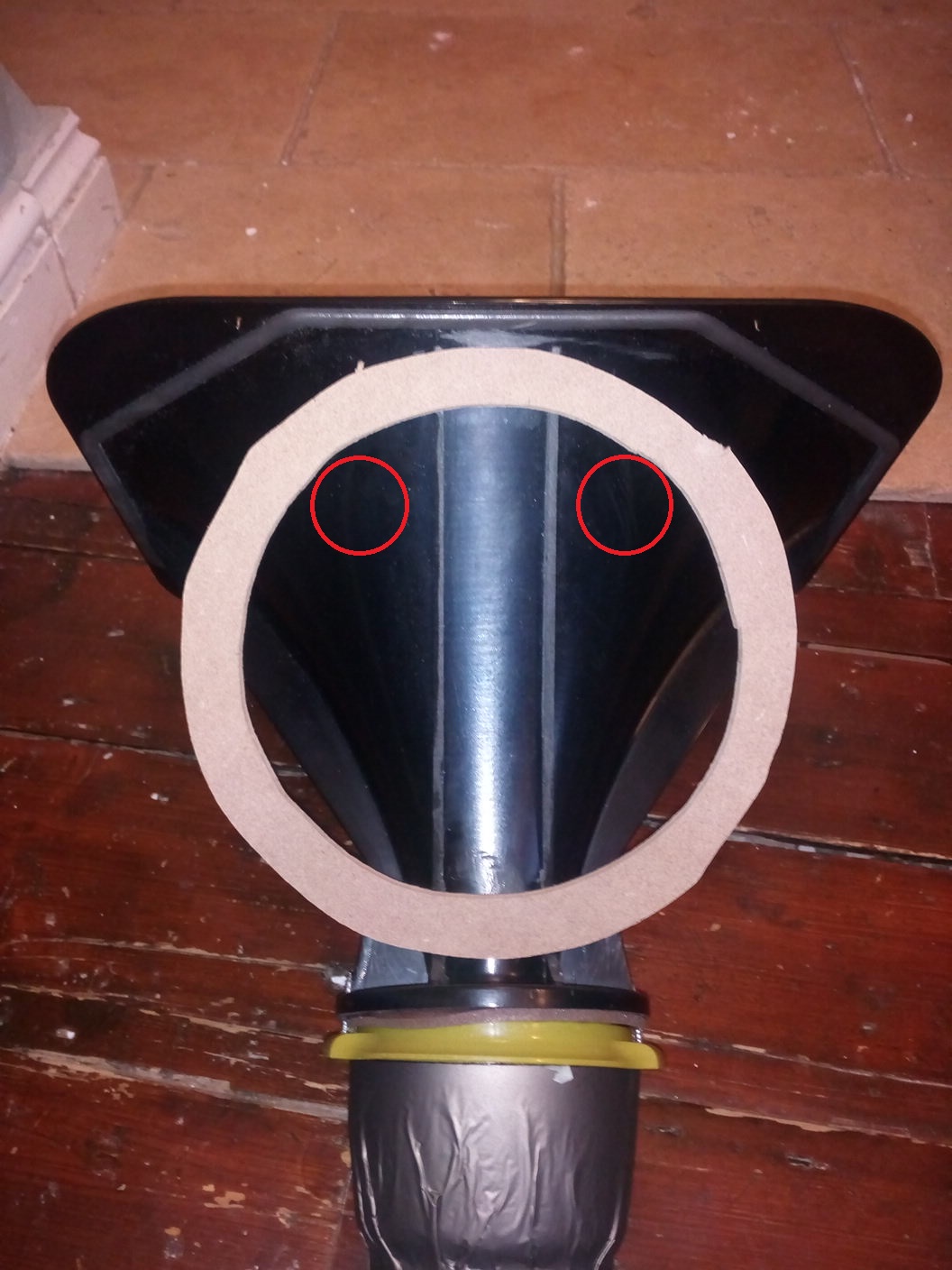
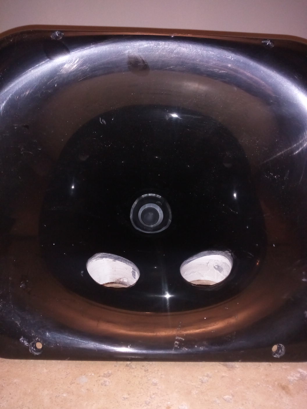
I decided the best way to achieve this would be via a smooth transition from cone surround to horn throat. And the best way to do this would be by routing the throat out to 2.5 inches with a smooth curve and modifying the driver bezel to allow a solid, smooth, diffraction free transition.
This is what I came up with:
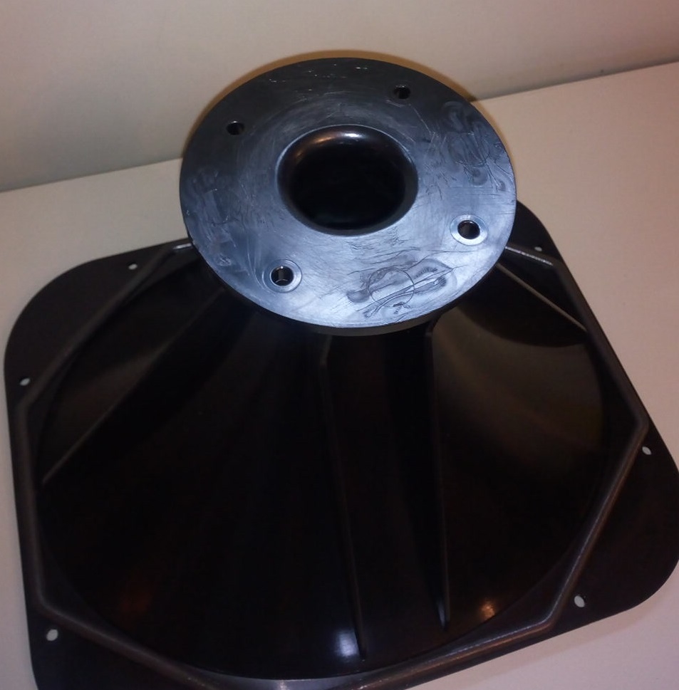
As you can see a nicely polished, smooth throat transition – important for a clean FR.
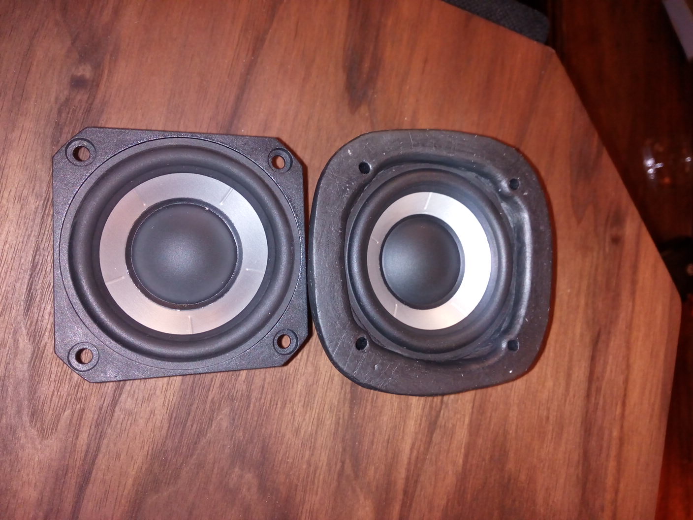
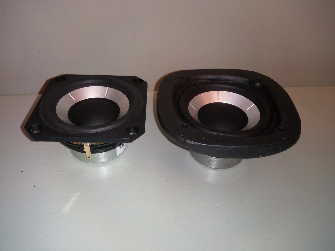
Stock bezel on the left. I used milliput to build up the bezel so it could be screwed into the horn and created the correct gap to allow the surround to move, whilst maintaining the curve into the throat.
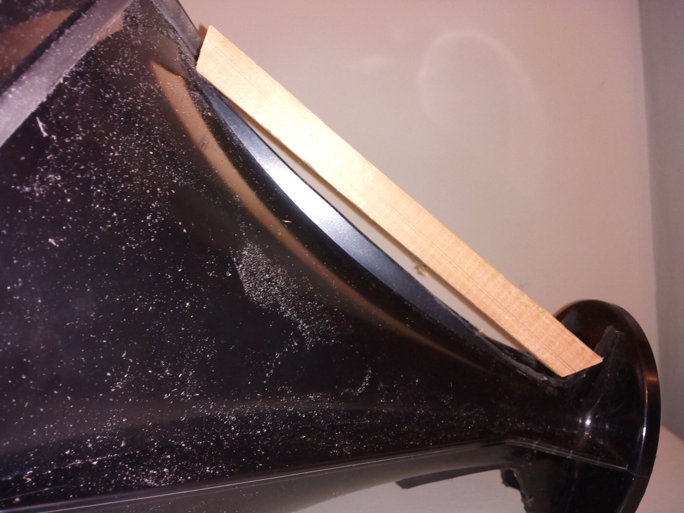
Here is a diagram to explain what I was trying to achieve:
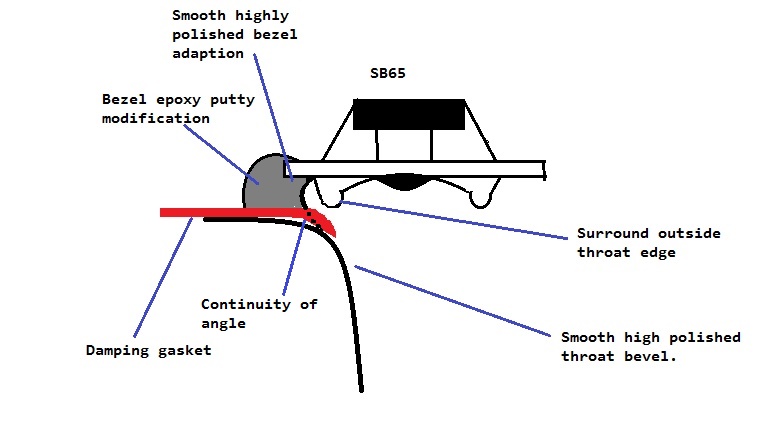
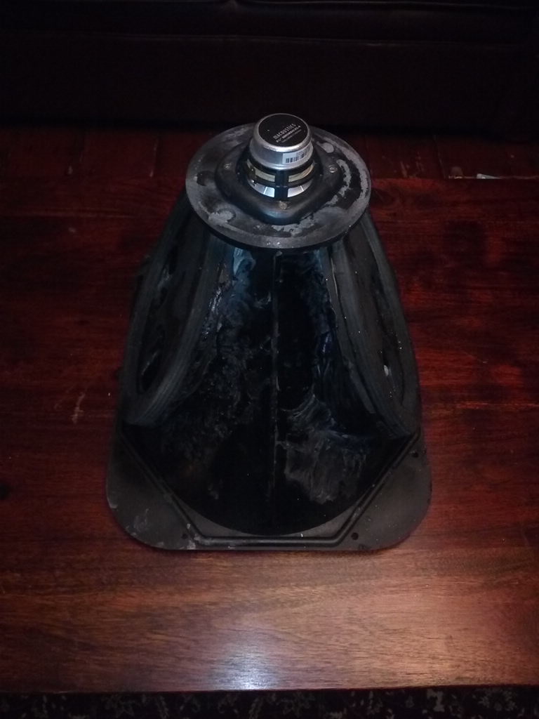
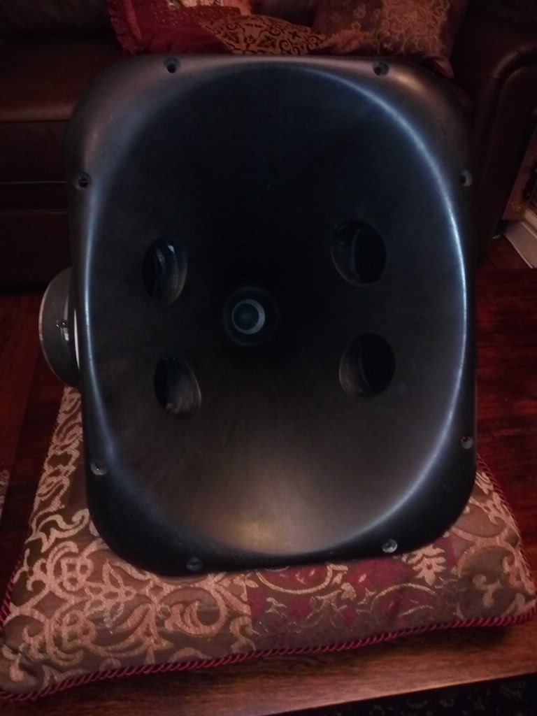
It allowed me to mount the SB65 perfectly aligned with the throat and the cone was then nicely sized to the throat diameter (as planned):
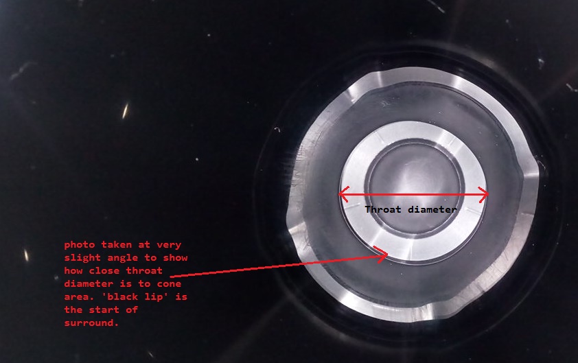
And with the addition of some wool felt around the throat I managed to get a smooth FR without any throat cancellations which had been a problem in previous horn loaded full range driver builds:
Before throat modifications – see cancellation dip at 6kHz.
After throat modifications.
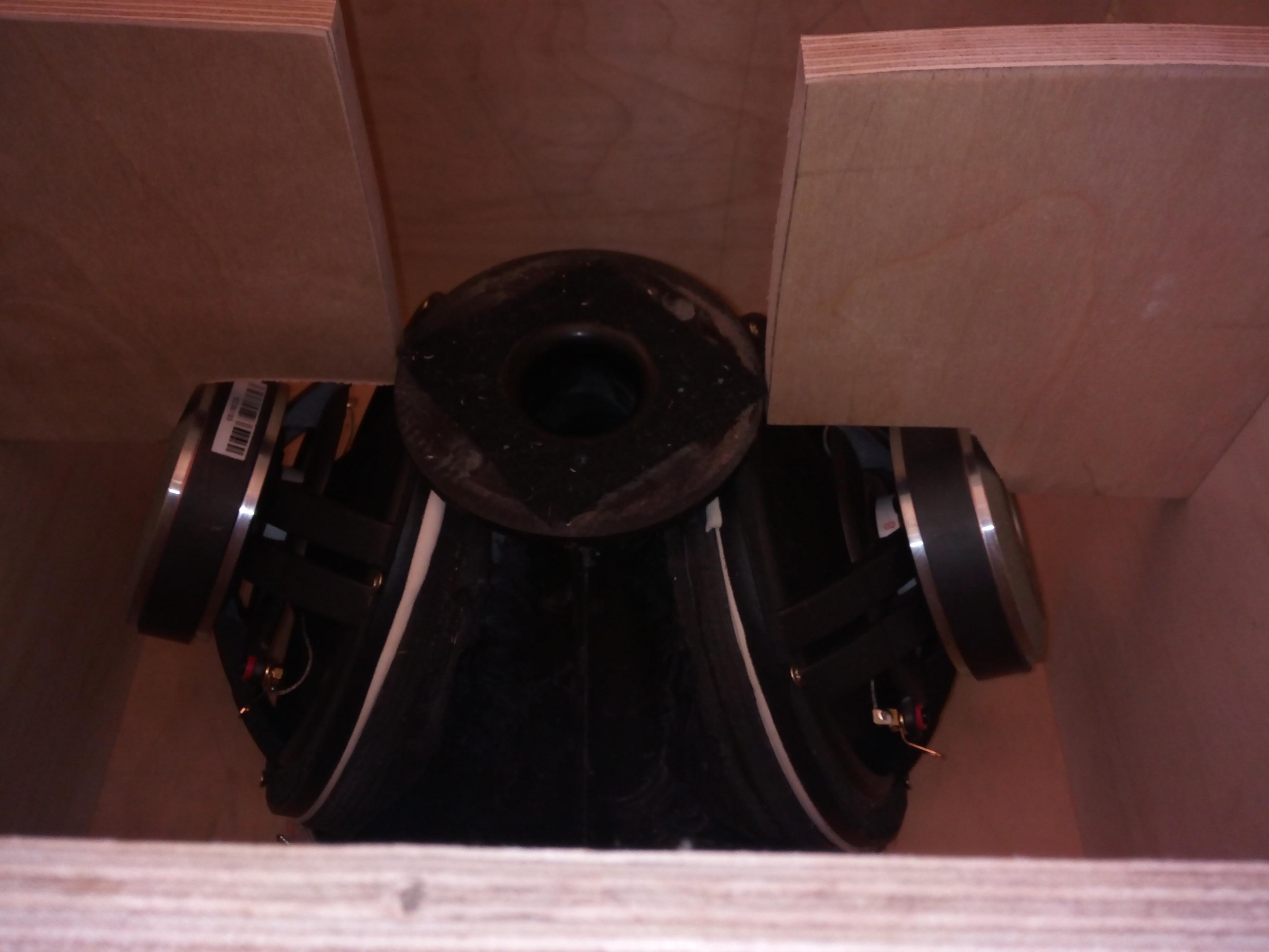
Next was mounting the woofers…
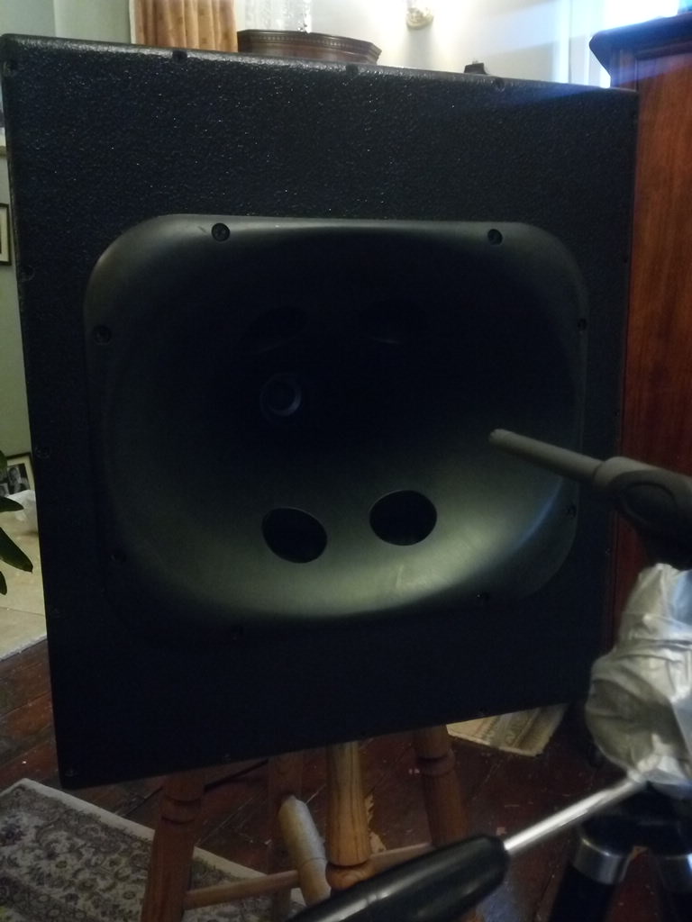
Given the external angle of the horns I knew I would have to grind down the strengthening ribs of the horn, then infill the gap with a two part epoxy up to a ply mounting plate. We decided to put the synergy taps approx. 20cm from the horn throat in order to minimise diffraction effects whilst keeping to almost ¼ wavelength distance at approx. 500hz.
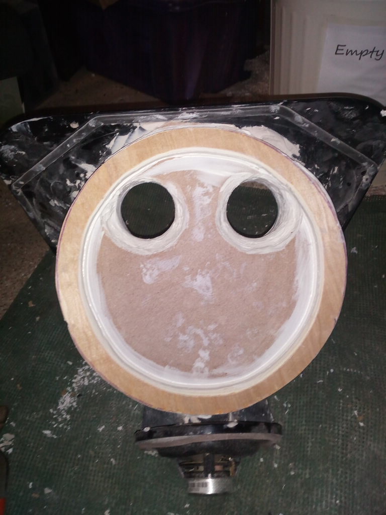
Once the ply wood plates were mounted, the ports/taps were drilled through with a 5.5cm circular saw. A 12mm ply ring was cut to allow full cone movement without mechanical rubbing of the surround.
Over 4Kg of two part epoxy was used, combined with the plywood, this made the horns very ‘dead’ and strong.
For the SB65 enclosure I used some old Tupperware bowls. About 3mm thick, very innately well damped as the plastic was not rigid, volume of 0.8l for a sealed qtc of 0.8ish, which given the crossover of ~600hz is fairly irrelevant anyway. These were damped with 4mm silentcoat for extensional damping, then 2mm rubber mat bonded to 15mm wool felting (this is an expensive underlay that uses 100% recycled wool felt and I have found works really well in speakers) - for further damping and absorption of reflections. They were then stuffed with rock wool insulation.
For the whole horn enclosure, I decided to increase the size compared to the sims (approx. 10 litres per woofer), in order to hopefully get better bass extension, allow for extensive cabinet damping treatments and bracing, whilst trying to keep the width to a minimum.
I decided to use 18mm high grade birch ply with extensive solid oak internal cross bracing and the same damping strategy as in the SB65 rear chamber – extensional damping with silentcoat – a polymeric based damping material, then the underlay - 2mm rubber mat bonded to 15mm 100% wool felting, then heavy rock wool stuffing. This combination in all my other builds has provided the best reduction in ‘box colouration’.
I therefore opted for a box size:
18 inches wide (the horn is 15 inches wide) so with the 18mm ply wood this allows 1 inch either side clearance - just enough for damping, rubber and felt layers with a few mm to spare.
20 inches tall - Horn is 12 inches tall, but with woofers mounted on largest sides each woofer adds 2.5 inches height. So again - just over an inch clearance either side.
16 inches deep - to accommodate the rear chamber of the SB65.
I figured this would give a box volume of approx. 45 litres after bracing/horn+driver volume/damping etc.
I also wanted to employ a magnet and horn ‘cradle’ which would firmly hold the horn and woofer magnets in a sorbothane damped plywood cradle. In previous experiments I found magnet mounting like this greatly reduced transference of mechanical energy into the cabinet – again massively reducing cabinet noise – by reducing cabinet resonances.
As you can tell – I had decided to go all out on cabinet optimization! This was mainly because I felt this project had such potential.
A few pictures are probably more explanatory:
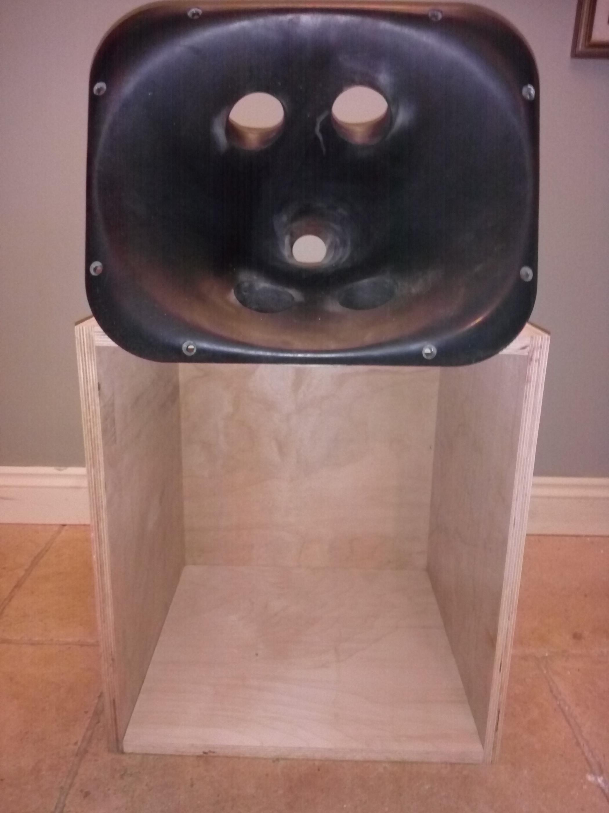
This is the ‘cradle’ – ‘holding’ the horn mounting plate, and both woofer magnets.
Those contact points then had 3mm sorbothane sheeting applied to provide damping.
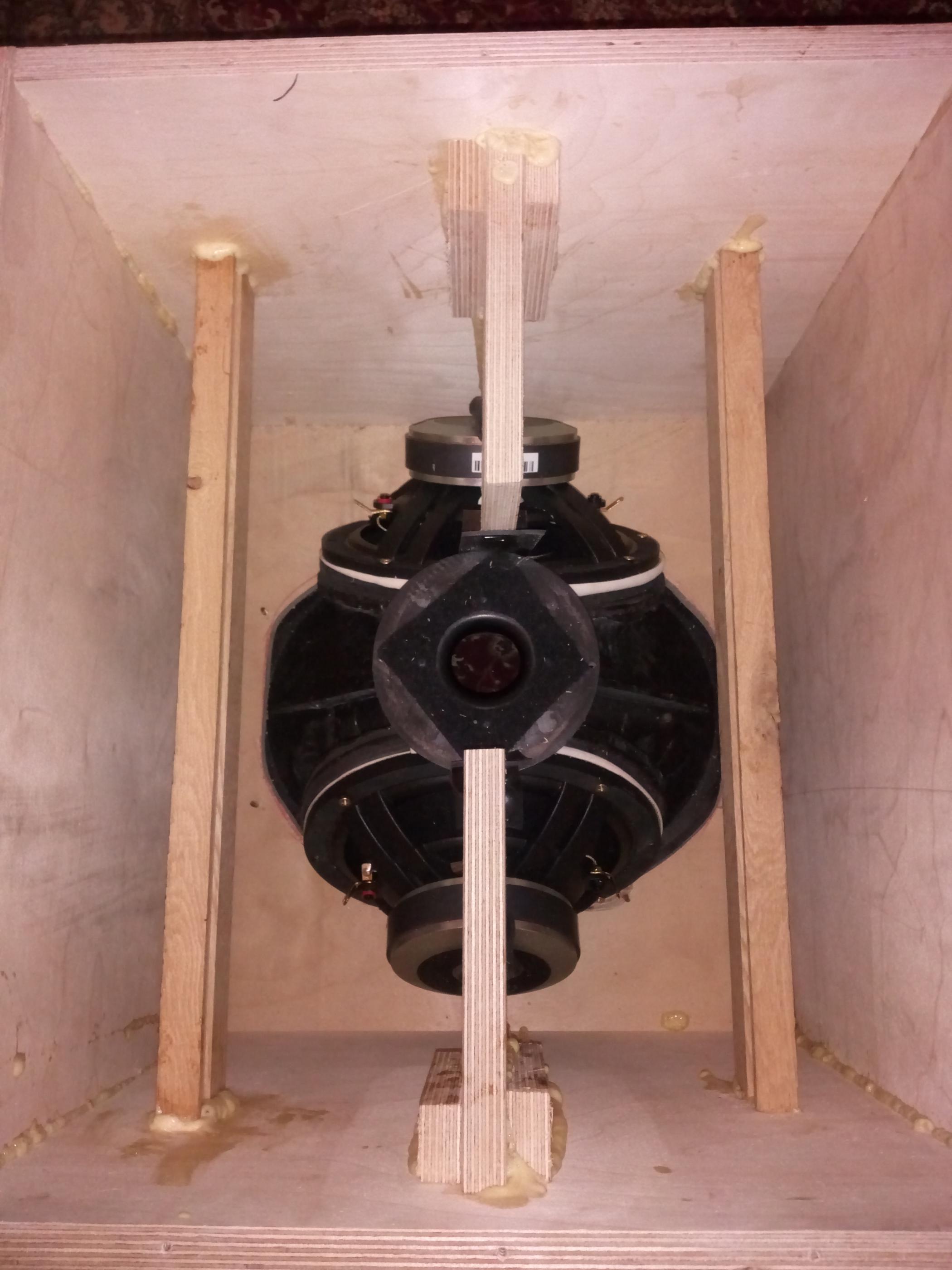
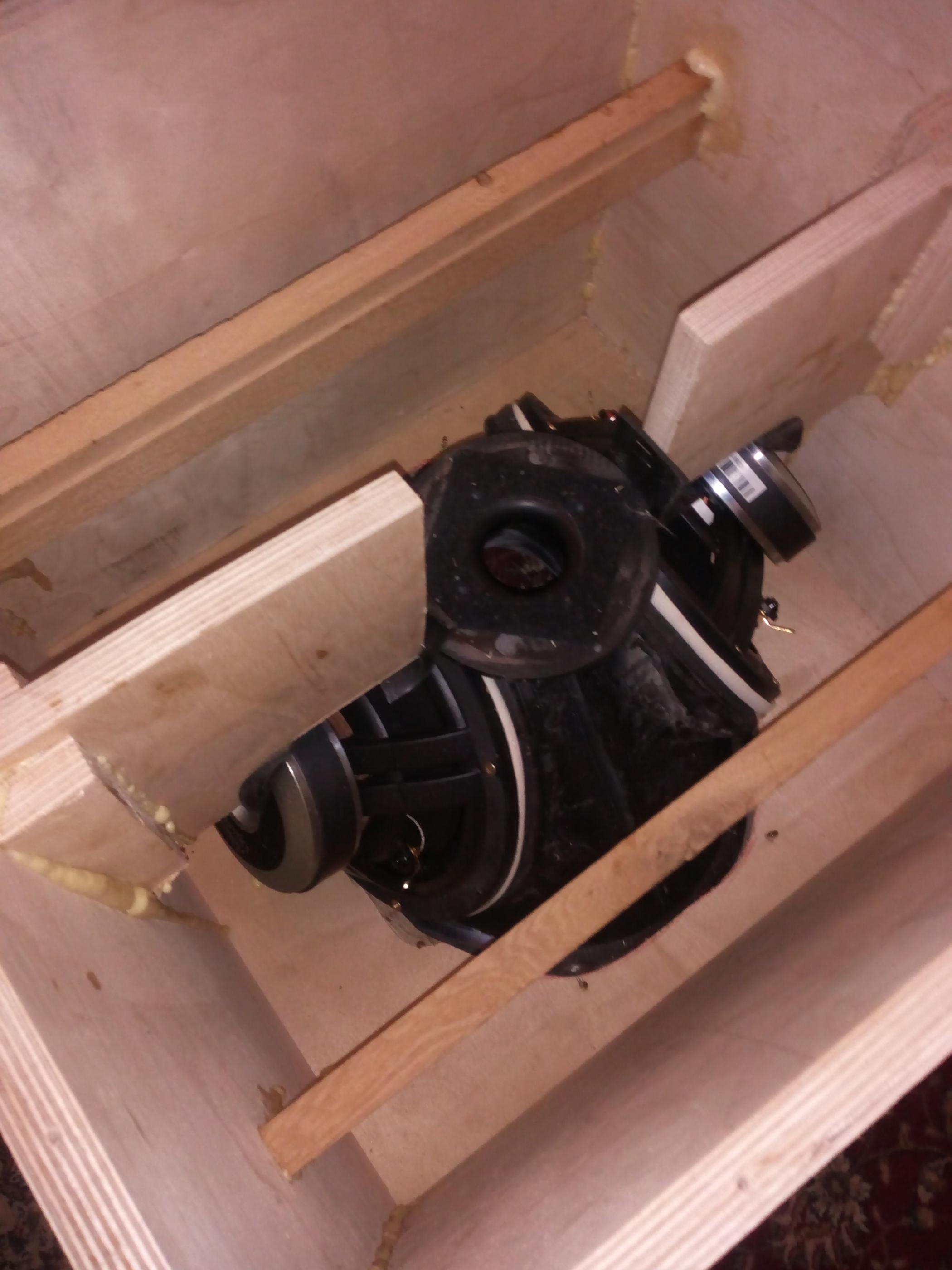
Cradle in situ holding horn. First oak crossbraces.
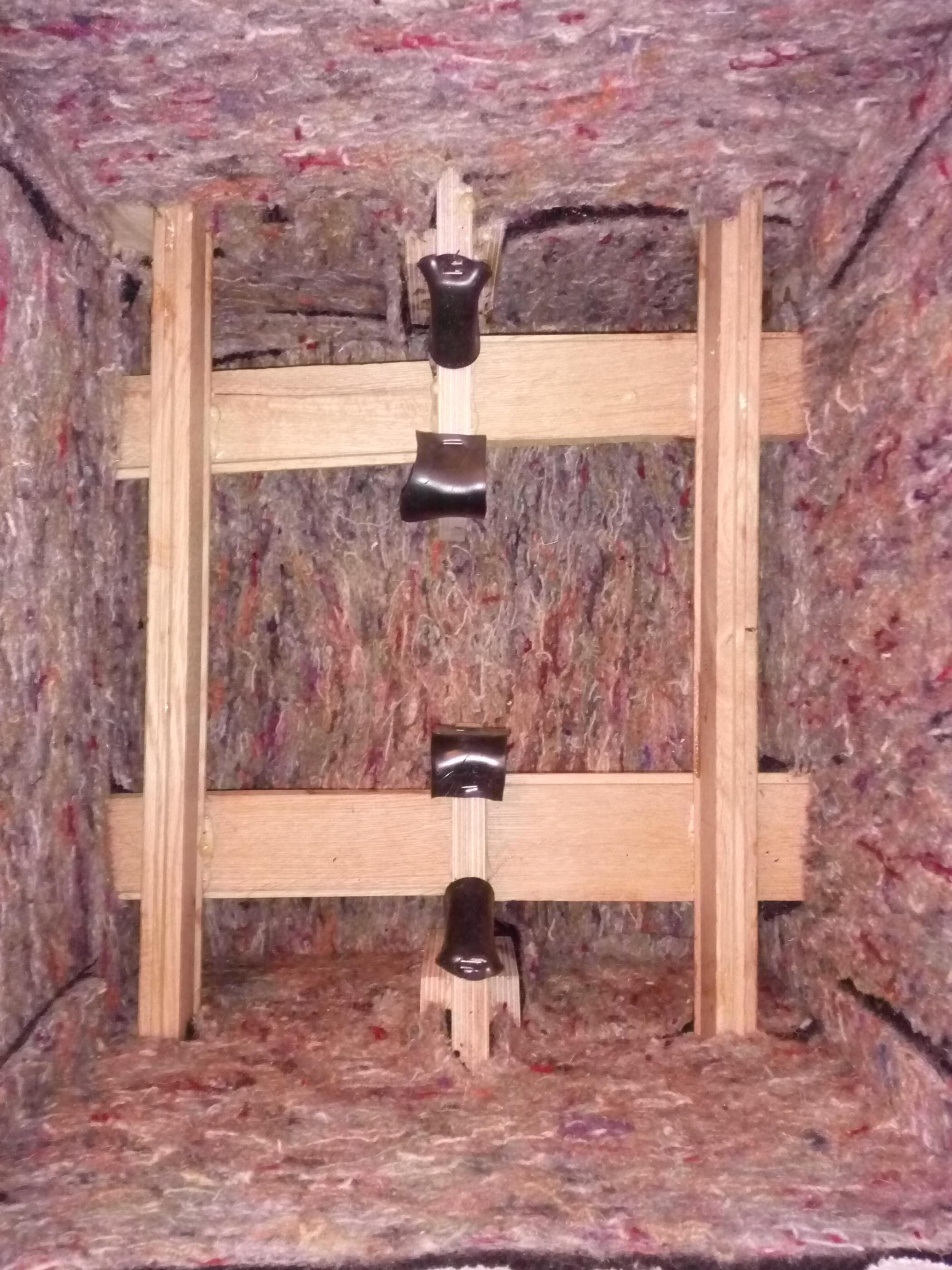
This is with silent coat, rubber, and wool felting applied to all internal surfaces. Also further oak braces added.
I then painted them black and started taking measurements…..
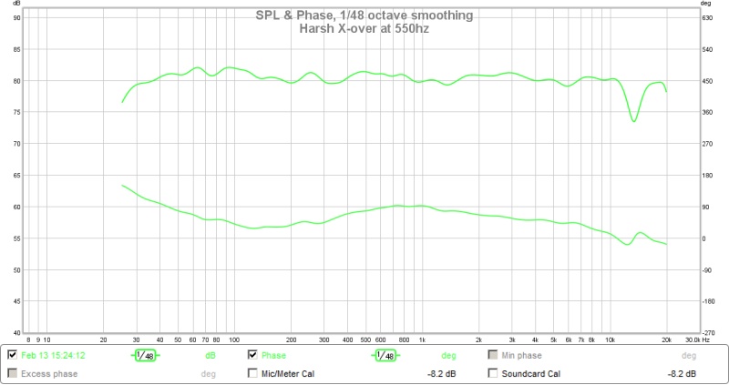
This speaker is designed using DSP – the miniDSP 4x10HD to be exact. I designed the crossover with the help of Xrk971 and Brytt, using a ‘harsh’ type crossover – well described in DIYaudio. This provides excellent phase results.
The speaker was designed to combine the advantages of SOTA modern CD horns, low crossover point and HD from horn loading a full range driver, the point source behaviour of a synergy layout, and cabinet optimizations to take full advantage of the above.
But the measured results were better than expected.
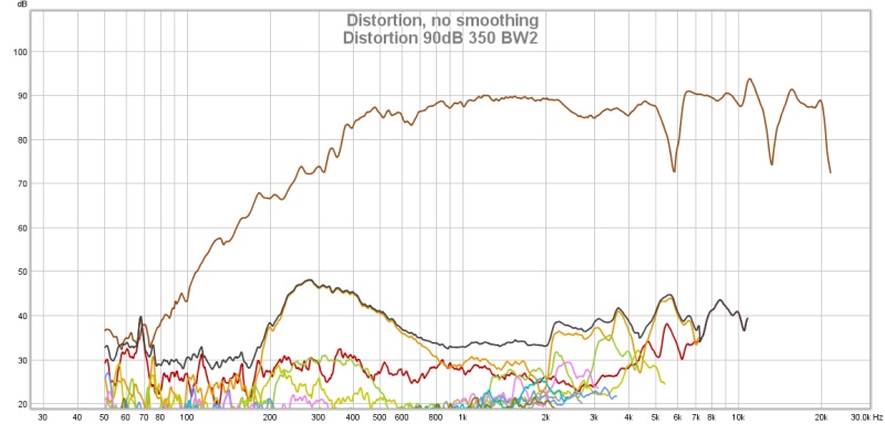
As you can see after experimentation the best x-over point appeared to be approx. 600hz – a play-off of SB65 low end distortion and the band limiting nature of the woofer synergy taps.
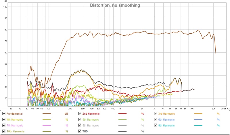
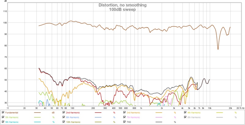
This provided fairly impressive distortion figures:
Very nice phase results:
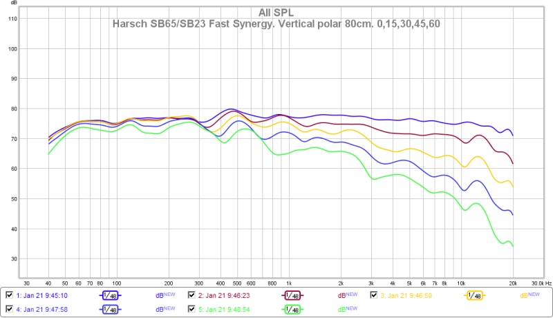
Excellent CD – down to 500hz horizontally and completely point source lobe free behaviour as predicted with the synergy design:

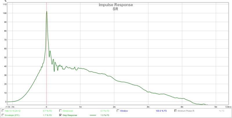
A nice step response:
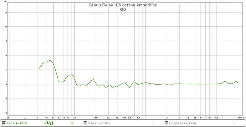
And Group delay:
I hope this summary helps people replicate this project if they wish.
A 2-way synergy speaker using full range drivers.
Bushmeister.
This is a write up of the build of the X-Bush speaker – a collaborative project mainly between two DIYaudio members – Bushmeister and Xrk971.
This was spawned due to my interest in building a DIY synergy horn using a commercial SOTA CD horn rather than a plywood DIY synergy horn as previous DIY builds had done.
I reasoned that the newer CD horns were designed using Computer Aided Finite Element Analysis to avoid the disadvantages usually associated with traditional diffraction/straight sided horns and therefore if this SOTA technology could be combined with synergy loading techniques, the best of both worlds might be achieved.
I was set to build one using a CD for treble and small mid drivers – in the more usual implementation of synergy horns – probably as a 3-way. Then I spotted xrk971’s experiments with full range horn loaded drivers.
He hadn’t tried a full range driver on a commercial horn, but had experienced promising results on his home cooked foam core horns. The most interesting results were in substantially lower HD than CDs, and the ability to run the full range driver down to 500Hz, allowing a 2-way crossover to a woofer rather than a mid-driver.
I immediately felt this would be a better technique than using a CD for treble – lower HD is always nice, but I was worried placing mid driver taps very close into the horn throat would largely be of detriment to the SOTA horn I was planning on using. A 2-way approach crossed over approx. 500-600 Hz would allow the woofer tap placement nearer the mouth of the horn, and still keep them within ¼ wavelength (important for the synergy design to work).
So after much reading on CD horn designs, I chose the Eighteen Sound elliptical shape technology (ESS), XT1464 constant coverage high frequency horn.
This provided a 60x40 degree pattern control horn down to almost 500Hz horizontally – key ingredients in my design choices. I didn’t want the speaker to be wider than 18” or so, yet I wanted good control to 500Hz as this seemed to be an important minimum CD frequency.
So I ordered the horns.
The next choice was the full range driver to match to the horn. Again, I was largely inspired by the work of Xrk971 – his full range driver threads and horn experiments led me to believe the two best candidates were either the TC9 or the SB65WBAC25.
Given the throat size of the XT1464 (1.4 inches) I knew the TC9 would be too large, so I ordered two SB65WBAC25s.
At this point I was planning on embarking on modelling the drivers on the horn and various injection port sites etc. i.e. doing this all on my own. However, when I mentioned my intentions on DIYaudio Xrk971 immediately offered to help me with the modelling and planning. As he is incredibly talented with software speaker modelling, whilst I enjoy the practical building and engineering challenges, it seemed like a perfect collaborative project (even if we were geographically ~4000 miles from each other).
I promptly measured up the horns so he could model a 3D form and things then began to move very swiftly…..
Xrk quickly discovered the SB65 were greatly assisted by the horn loading, to such a point that despite the 2.5mm X-max they would likely have greater output than the woofers I had initially chosen:
SB65WBAC25-4 -max-SPL
As can be seen the SB65 would run up past 120dB within X-max, and is actually only limited thermally. This led me to look into some more capable woofers for the two way implementation.
I like SB acoustics offerings and their SB23NRXS45-8 8” woofers caught my eye. It seemed to have ideal TS parameters, was very low distortion and had ideal physical dimensions to mount onto the XT1464 neatly.
I ran it past Xrk971, who promptly modelled it at x-max to see if the dual 8” woofers could keep up with the small SB65 horn loaded full range unit:
SB23RNXS45-8-SB65WBAC25-4-350Hz-12db-xmax-limit-max-SPL-78v
You can see it is impressive how the tiny SB65 keeps up with the two 8” units.
sb23nrxs45-8-max-SPL-Displ- -65Hz-HPF
As can be seen, they were an ideal match – similar max outputs, the SB65 being thermally limited, whilst the SB23 were x-max limited (see excursion plot).
It was also interesting to note how the horn loading had affected sensitivities and how low the excursion was at ‘normal’ sound pressure levels (I believe this is central to the reasons this design has such low HD).
sb23nrxs45-8-SPL-Sensitivity-2.83v-65Hz-HPF
sb23nrxs45-8-SPL-Displacement-at-2.83v- -65Hz-HPF
As you can see at 95dB (the Xbush sensitivity at 2.83v) the woofers are only moving 0.7mm, and the SB65 a mere 0.1mm (100 microns). So no wonder HD is very low.
I then began the engineering task of working out how to put the pieces together to do justice to the sims!
The first problem was mounting a 2.5” full range driver onto a horn designed for a bolt on 1.4” CD.
I decided the best way to achieve this would be via a smooth transition from cone surround to horn throat. And the best way to do this would be by routing the throat out to 2.5 inches with a smooth curve and modifying the driver bezel to allow a solid, smooth, diffraction free transition.
This is what I came up with:
As you can see a nicely polished, smooth throat transition – important for a clean FR.
Stock bezel on the left. I used milliput to build up the bezel so it could be screwed into the horn and created the correct gap to allow the surround to move, whilst maintaining the curve into the throat.
Here is a diagram to explain what I was trying to achieve:
It allowed me to mount the SB65 perfectly aligned with the throat and the cone was then nicely sized to the throat diameter (as planned):
And with the addition of some wool felt around the throat I managed to get a smooth FR without any throat cancellations which had been a problem in previous horn loaded full range driver builds:
Before throat modifications – see cancellation dip at 6kHz.
After throat modifications.
Next was mounting the woofers…
Given the external angle of the horns I knew I would have to grind down the strengthening ribs of the horn, then infill the gap with a two part epoxy up to a ply mounting plate. We decided to put the synergy taps approx. 20cm from the horn throat in order to minimise diffraction effects whilst keeping to almost ¼ wavelength distance at approx. 500hz.
Once the ply wood plates were mounted, the ports/taps were drilled through with a 5.5cm circular saw. A 12mm ply ring was cut to allow full cone movement without mechanical rubbing of the surround.
Over 4Kg of two part epoxy was used, combined with the plywood, this made the horns very ‘dead’ and strong.
For the SB65 enclosure I used some old Tupperware bowls. About 3mm thick, very innately well damped as the plastic was not rigid, volume of 0.8l for a sealed qtc of 0.8ish, which given the crossover of ~600hz is fairly irrelevant anyway. These were damped with 4mm silentcoat for extensional damping, then 2mm rubber mat bonded to 15mm wool felting (this is an expensive underlay that uses 100% recycled wool felt and I have found works really well in speakers) - for further damping and absorption of reflections. They were then stuffed with rock wool insulation.
For the whole horn enclosure, I decided to increase the size compared to the sims (approx. 10 litres per woofer), in order to hopefully get better bass extension, allow for extensive cabinet damping treatments and bracing, whilst trying to keep the width to a minimum.
I decided to use 18mm high grade birch ply with extensive solid oak internal cross bracing and the same damping strategy as in the SB65 rear chamber – extensional damping with silentcoat – a polymeric based damping material, then the underlay - 2mm rubber mat bonded to 15mm 100% wool felting, then heavy rock wool stuffing. This combination in all my other builds has provided the best reduction in ‘box colouration’.
I therefore opted for a box size:
18 inches wide (the horn is 15 inches wide) so with the 18mm ply wood this allows 1 inch either side clearance - just enough for damping, rubber and felt layers with a few mm to spare.
20 inches tall - Horn is 12 inches tall, but with woofers mounted on largest sides each woofer adds 2.5 inches height. So again - just over an inch clearance either side.
16 inches deep - to accommodate the rear chamber of the SB65.
I figured this would give a box volume of approx. 45 litres after bracing/horn+driver volume/damping etc.
I also wanted to employ a magnet and horn ‘cradle’ which would firmly hold the horn and woofer magnets in a sorbothane damped plywood cradle. In previous experiments I found magnet mounting like this greatly reduced transference of mechanical energy into the cabinet – again massively reducing cabinet noise – by reducing cabinet resonances.
As you can tell – I had decided to go all out on cabinet optimization! This was mainly because I felt this project had such potential.
A few pictures are probably more explanatory:
This is the ‘cradle’ – ‘holding’ the horn mounting plate, and both woofer magnets.
Those contact points then had 3mm sorbothane sheeting applied to provide damping.
Cradle in situ holding horn. First oak crossbraces.
This is with silent coat, rubber, and wool felting applied to all internal surfaces. Also further oak braces added.
I then painted them black and started taking measurements…..
This speaker is designed using DSP – the miniDSP 4x10HD to be exact. I designed the crossover with the help of Xrk971 and Brytt, using a ‘harsh’ type crossover – well described in DIYaudio. This provides excellent phase results.
The speaker was designed to combine the advantages of SOTA modern CD horns, low crossover point and HD from horn loading a full range driver, the point source behaviour of a synergy layout, and cabinet optimizations to take full advantage of the above.
But the measured results were better than expected.
As you can see after experimentation the best x-over point appeared to be approx. 600hz – a play-off of SB65 low end distortion and the band limiting nature of the woofer synergy taps.
This provided fairly impressive distortion figures:
Very nice phase results:
Excellent CD – down to 500hz horizontally and completely point source lobe free behaviour as predicted with the synergy design:
A nice step response:
And Group delay:
I hope this summary helps people replicate this project if they wish.
Imagine what can be done with FIR convolution on top of the already good xBush performance. I'm glad Bushmeister will go along and get all this data at the LP. To compare that to a conventional open radiator speaker will be very interesting.
Edit: just saw the excellent summary. Thanks!
I will put a link to it in first post and clean up post 1 to remove extraneous progress reports.
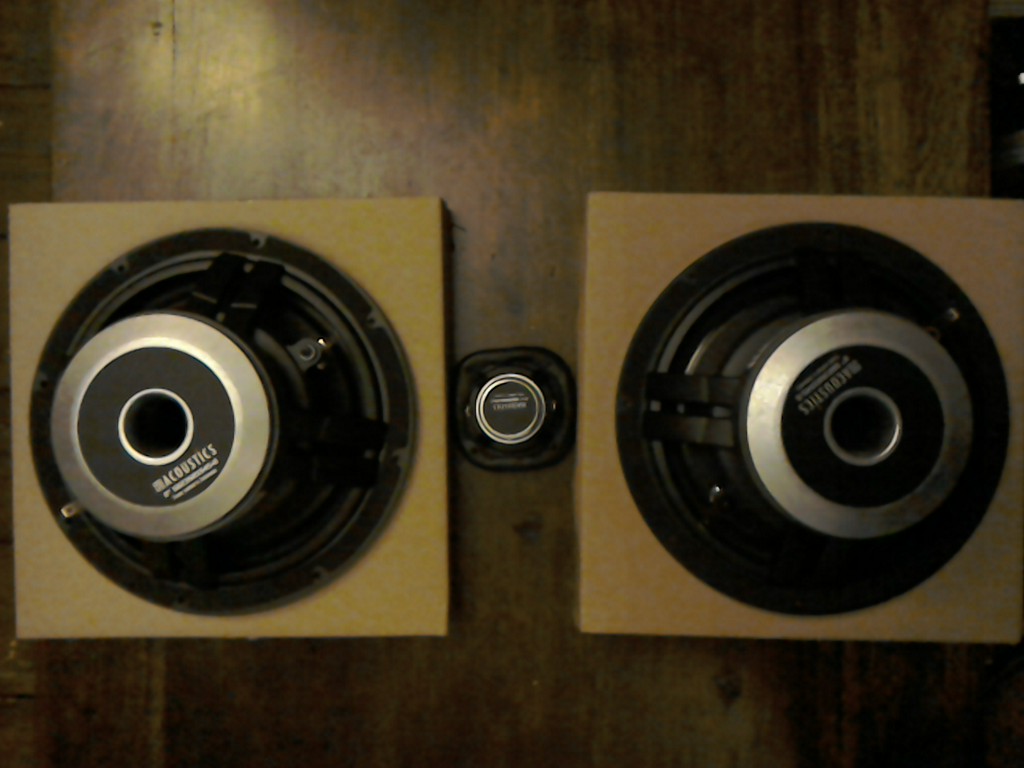
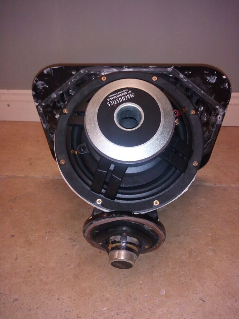
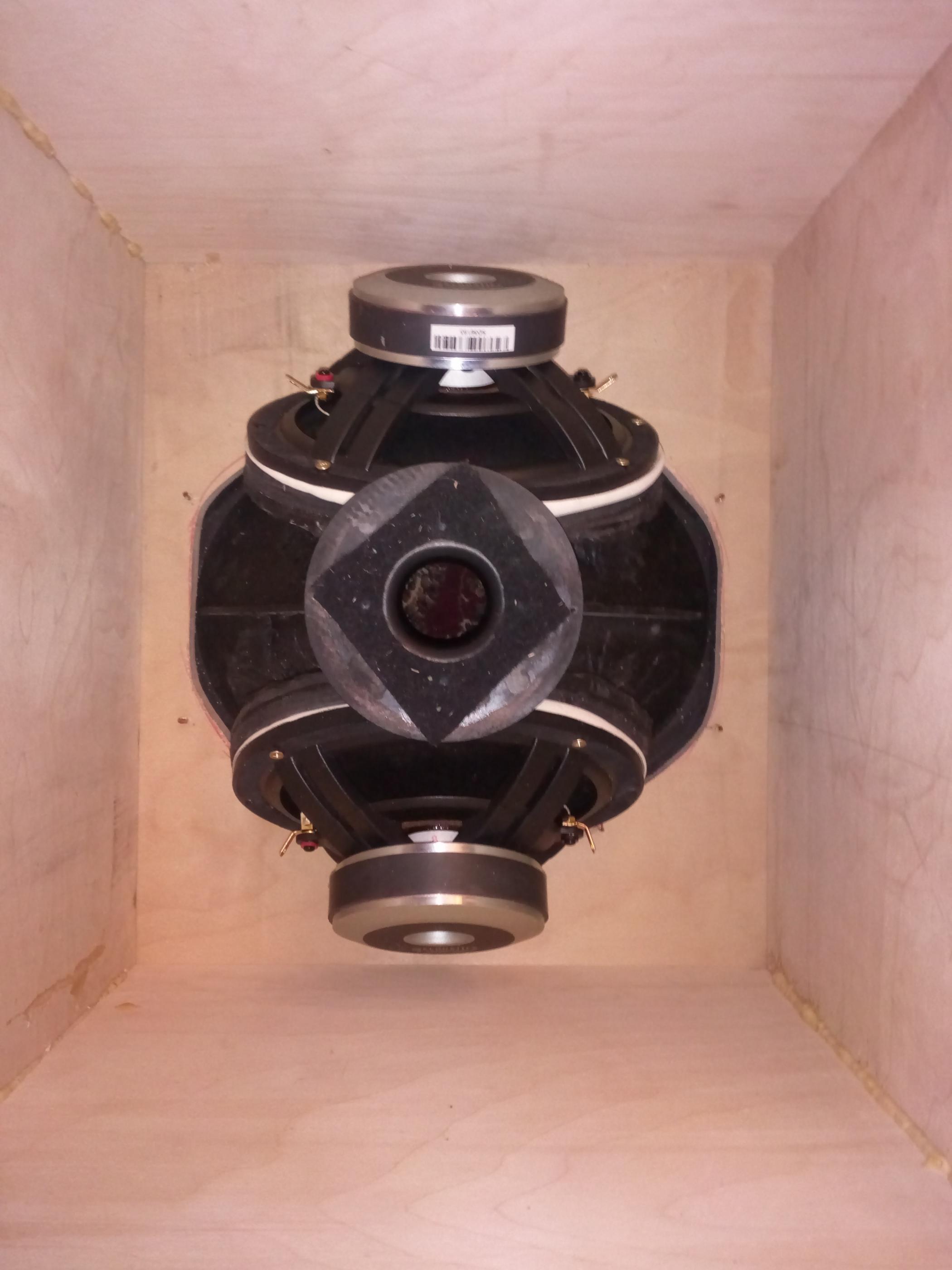
This is a great photo I have not seen before. It shows the massive scale of the woofers vs the tiny full range. These SB23's are much bigger than my RS170P's.
Edit: just saw the excellent summary. Thanks!
I will put a link to it in first post and clean up post 1 to remove extraneous progress reports.
This is a great photo I have not seen before. It shows the massive scale of the woofers vs the tiny full range. These SB23's are much bigger than my RS170P's.
Last edited:
Imagine what can be done with FIR convolution on top of the already good xBush performance.
😱 🙂
May i ask why? It was ugly?
Even i hate the look did it again and please don't compare to wesayso's 😛
Attachments

Even i hate the look did it again and please don't compare to wesayso's
Ronald's results are from intensive effort and treatments! I don't doubt if you follow same way it could end up the same (more or less).
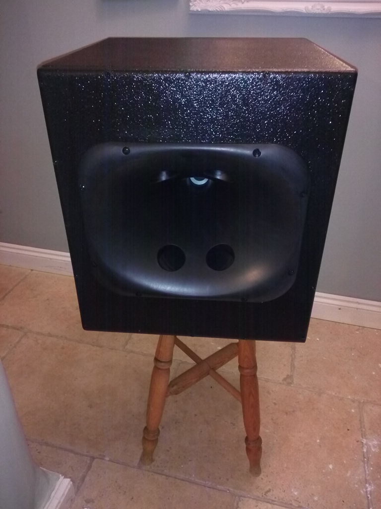
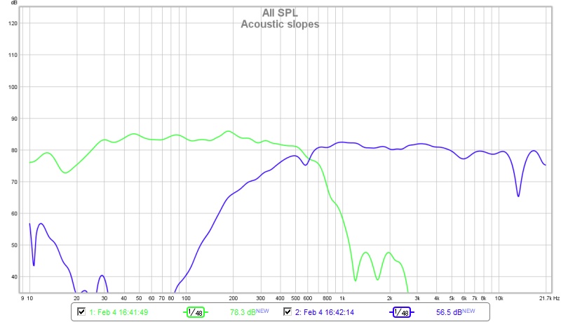
From your graph you have a nice bounce floor issue at 2.5m (130hz area in wavelet) and some room mode 30/40hz, ER issue in the 250/500hz range: pretty standard issue for home environnment not this bad as a start point. Probably a room mode at 100hz too. From 1k and up this is not too bad.
From 30cm your speaker look nice!
Byrtt do you have a thread about your loudspeaker?
Very nice summary from you Bushmeister. It's easier to see all work you have done with X. It's even more impressive that way! 🙂
Last edited:
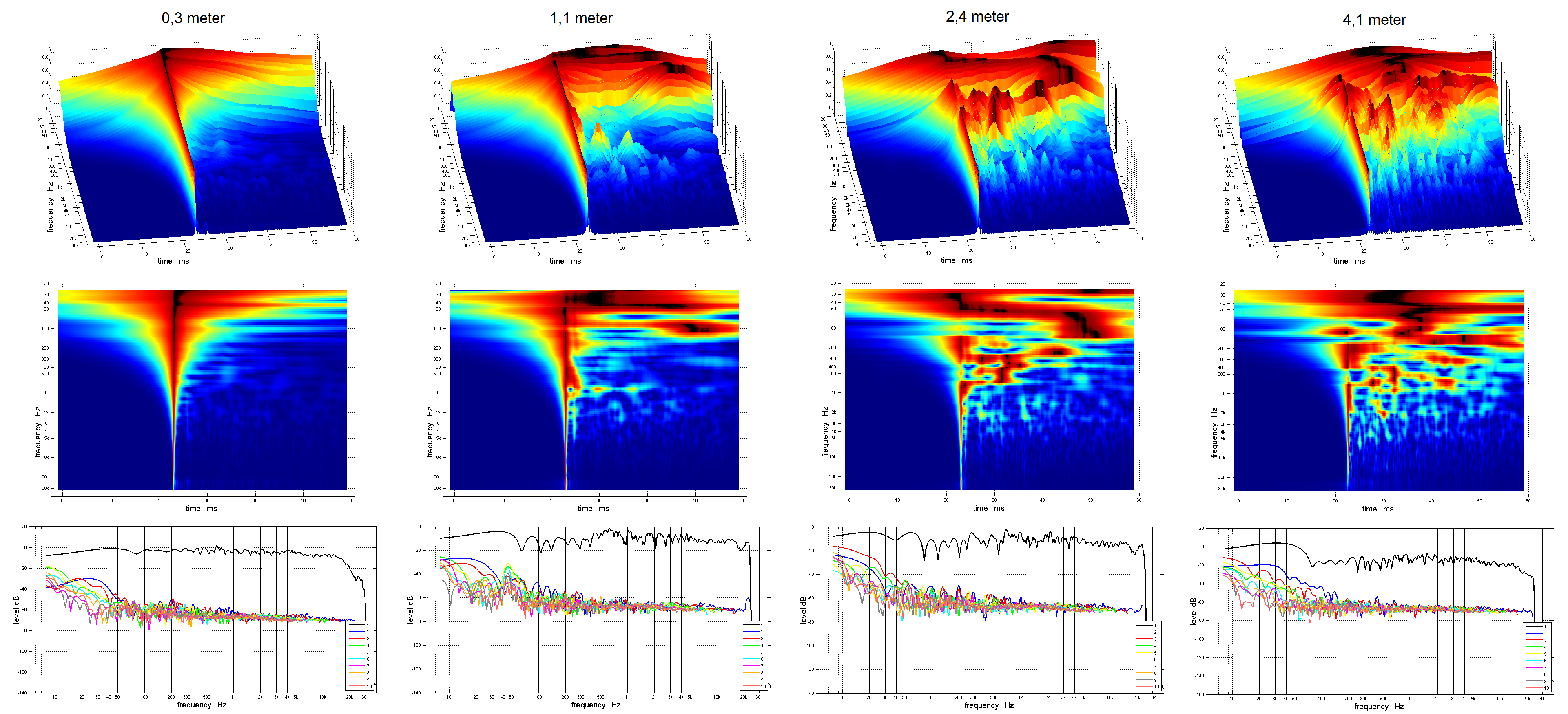
Thank you, BYRTT for having the guts to post it anyway. It sure demonstrates it is valid to look at the distance you are actually using to listen to it. We see much more room disturbance at the greater distance. Lots of little things that need a "cure". 🙂
Thanks Bushmeister, nice work, the smooth shaping with époxy is great like the clean ports 🙂
Phase and smooth directivity are impressive... max spl output as well !
Just a question please : how is made and glued the gasket between the Bezel and the throat ? Not apealed by directly a Bezel on the throat (like you did with époxy ports) ?
Anyway : Kudos for the skill work !
Phase and smooth directivity are impressive... max spl output as well !
Just a question please : how is made and glued the gasket between the Bezel and the throat ? Not apealed by directly a Bezel on the throat (like you did with époxy ports) ?
Anyway : Kudos for the skill work !
Thanks analyze krivium and wesayso, will look forward to learn from upcoming exercise with bushmeisters serious speaker builds.
Krivium speaker is a exercise to learn so no thread before settle on some more serious enclosure stuff, drivers is 10F/8424 and SPH-250KE, a picture is to find over here at Raimonds thread in post 166 http://www.diyaudio.com/forums/full...do-dsp-power-now-availabl-17.html#post4624596.
Krivium speaker is a exercise to learn so no thread before settle on some more serious enclosure stuff, drivers is 10F/8424 and SPH-250KE, a picture is to find over here at Raimonds thread in post 166 http://www.diyaudio.com/forums/full...do-dsp-power-now-availabl-17.html#post4624596.
Ronald, in the 3d graph vertical axis is level but what is the unit? 1 equal max spl produced and then this is relative level (0.5x max spl, 0.3x max spl,...)?
Ronald, in the 3d graph vertical axis is level but what is the unit? 1 equal max spl produced and then this is relative level (0.5x max spl, 0.3x max spl,...)?
I've asked the same question to Raimonds Skuruls, but up to this point I'm really not sure. Knowing my room from REW measurements I could take a shot at it but I'd rather hear it from Mr. Skuruls himself.
Another thing to note is those plots are normalized, which is obvious by looking at it.
Here's a link (including the result in a marvelous room from member jim1961): APL_TDA thread
Why not show the IR and STEP, as measured at the listening position, along with the filtered IR and a spectrogram (to about 30 ms), or even better an APL_TDA plot.
If you do this, show the first ~25 ms in the IR, STEP can be in the same plot at that scale. The filtered IR could show 300 ms, and about 60 dB down from the top peak. The spectrogram about 30 ms (to show the early wave front) and for starters down to 25 dB?(*) That would show a lot of room for most type of speakers. Lately I love to look at how APL_TDA plots show it, you can still "see" the room. But a combination of both shows even more.
All three of them would/should show if there's less room interaction. Not trying to be a bore here. But as long as we are playing, let's see the graphs that support the speculation. That's the reason why I have posted that many graphs on my own thread. Let's learn how these things look and what the differences are. Not at 0.5 meter but at the listening position. In the end, that's where the magic should happen 🙂.
I'm hoping you're willing to play along 😉. Even better if you show it from the conventional speaker as well. Then we can compare even more data. In the end, the measurements should be able to tell us a story. All of the combined views should teach us where to look. Not the semi ideal close up measurements, the ones at the listening position, that's where we listen after all.
Sure, I know a filtered IR isn't telling everything, but we've got to start somewhere. Are you guys willing to play? I'd love to see that data. Even the early waterfall plots like I've asked about earlier on the thread tell me something. Let's learn people! Stop guessing, at least as far as we can. There will be enough left to guess about, I promise 😉. There's still more to be seen of coarse, but there's hardly any data like this around! Let's start somewhere! Sure this will be your room", but let's link a couple of these plots to what the subjective listening impressions say.
(*) = My spectrogram plots have only been to -15 dB and -20 dB for the most part, though I did post a -40 dB plot once. At -20 dB, it showed enough room interaction in my case, while the -15 dB plot was pretty clean. All taken at the listening position. I believe this is a great way to learn a bit more.
OK I have an hour or so now....
So lets do my three way prestige first.
Should I be measuring both speakers at once at the LP???
OK - I have no idea what I am doing with these LP measurements!!!
Here are some taken on standard settings.
Single speaker. From approx - 2.4m away.
Here are some taken on standard settings.
Single speaker. From approx - 2.4m away.
Attachments


Last edited:
- Home
- Loudspeakers
- Multi-Way
- A Bookshelf Multi-Way Point-Source Horn