Wow that was quick - I make a cup of coffee and you've done it already!
I reckon that looks much better - so that is approx 11 cm2 per port, which, to minimize loss of wave-guide I could cut as a 5.5x2cm radial slots.
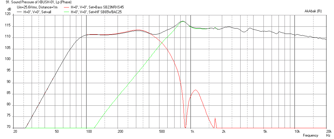
Looking at your sim, this also means I can cut the SB65 rather than boost it to match the outputs, thereby lowering thermal stress on the little driver.
I totally agree with doing sims first - It just amazes me what can be done with the software out there now.
I will put the order in tonight and get removing ribs from the horns.......
I reckon that looks much better - so that is approx 11 cm2 per port, which, to minimize loss of wave-guide I could cut as a 5.5x2cm radial slots.
Looking at your sim, this also means I can cut the SB65 rather than boost it to match the outputs, thereby lowering thermal stress on the little driver.
I totally agree with doing sims first - It just amazes me what can be done with the software out there now.
I will put the order in tonight and get removing ribs from the horns.......
Thanks! Once I have the code written, little tweaks are easy. The main code writing this morning took a few hours but as I work from previous saved code it is much easier.
You can design a lot with Akabak - not the easiest SW to use but very powerful and fast as you have seen. Text based code has efficiency vs point and click dialogs which have ease of use but are slow to modify.
The SB65 was already cut -2dB so maybe -3dB would be about right. Less stress, less movement for lower distortion. The radial slot holes are fine however you work it out so area is about the same. But a thin thin high aspect ratio (10:1) slit is a different story as there are wall skin friction losses. If it is an elliptical waveguide, I don't know where the best places to put the holes/slots are. I think avoid directly having them on left and right walls (easy) and keep them towards the corners, if there are any in an ellipse.
This should be very interesting and fun to build. I think it will sound great too.
Last edited:
If for 8" woofer i set 8 liter back box and 0,165 liter front box with 1kHz resonance then with two 65mm diameter injection ports program says their lengths should be 54mm, if instead i change setting to two 50mm diameter injection ports program says their lengths should be 20mm, so think we have a variable that if horn material plus plywood at port entrance can be brought down to 20mm will lower entrance area of port inside horn. Is this doable or am i wrong, it was same i pointed out for 4" woofers that if length was brought down (horn material plus plywood) from 30mm to 19mm then port area diameter could shrink from 34mm to 29mm.
OK - so if I can get the port length as low as possible - we can minimize cross-sectional area required?
Well luckily the horn itself is only a few mm thick - would be a different story if I had made it from scratch.
But also, presumably I can remove lots of material from inside the mounting plates - as described in the patents - thereby reducing the port length to only a few mm?
Well luckily the horn itself is only a few mm thick - would be a different story if I had made it from scratch.
But also, presumably I can remove lots of material from inside the mounting plates - as described in the patents - thereby reducing the port length to only a few mm?
You have your 12mm thick plywood mounting board to contend with - I have been using 30mm but Byrtt is right, the smaller you can make it, the more SPL you get for same CSA. Also cutting it out with a frustrum helps too.
I was reading the WG specs and it says it is made of compressed foam? Then coated with plastic?
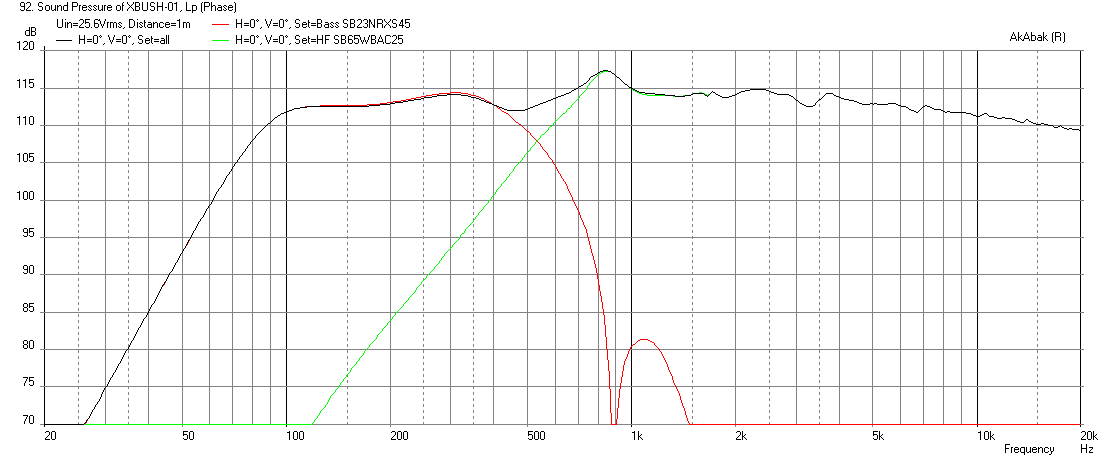
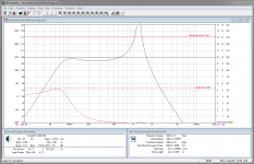
So if we assume we have a 12mm thick plywood driver board, and say the WG and glue is 4mm for 16mm length of inejction duct, we get 111.5dB. So yes we bought 1.5dB for free. Making the frustrum to reduce flow losses even more will only improve that.
These will probably be within THX required SPL capability for 105dB at listening position. Make 5 and you have THX HT with horns.
I was reading the WG specs and it says it is made of compressed foam? Then coated with plastic?
So if we assume we have a 12mm thick plywood driver board, and say the WG and glue is 4mm for 16mm length of inejction duct, we get 111.5dB. So yes we bought 1.5dB for free. Making the frustrum to reduce flow losses even more will only improve that.
These will probably be within THX required SPL capability for 105dB at listening position. Make 5 and you have THX HT with horns.
Attachments
Last edited:
Think not its a problem going up in port length then solution just use thicker plywood, problem is find acceptable port area entrance to not spoil dispersion for tweeter and not shorter length that horn material plus plywood in front of woofers resonance chamber will start rattle or go into resonance too if its too thin.
xrk971 if i set diameter area to 2 times 37mm ports for one woofer then length should be very short 1mm which is not doable, but is what you call frustum entrance the trick that port now is down to virtual 1mm in the lip at horn entrance.
xrk971 if i set diameter area to 2 times 37mm ports for one woofer then length should be very short 1mm which is not doable, but is what you call frustum entrance the trick that port now is down to virtual 1mm in the lip at horn entrance.
Last edited:
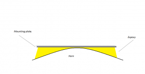
I have thought about the plywood thickness, and due to the curvature of the horn, the thickness of glue between the horn and the mounting plate will, toward the outer regions, probably be >1cm.
So if I use a dampening epoxy product, or structural adhesive, resonances will be no problem. The only point the mounting plate will be 'thin' - is the point I put the frustrum at.
So if I use a dampening epoxy product, or structural adhesive, resonances will be no problem. The only point the mounting plate will be 'thin' - is the point I put the frustrum at.
Last edited:
Think not its a problem going up in port length then solution just use thicker plywood, problem is find acceptable port area entrance to not spoil dispersion for tweeter and not shorter length that horn material plus plywood in front of woofers resonance chamber will start rattle or go into resonance too if its too thin.
xrk971 if i set diameter area to 2 times 37mm ports for one woofer then length should be very short 1mm which is not doable, but is what you call frustum entrance the trick that port now is down to virtual 1mm in the lip at horn entrance.
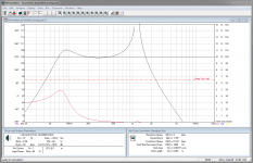
Byrtt, I think your model requires a length for a flow resistance as it is assuming a conventional bandpass chamber and bandpass port. For a bandpass injection, the length of the port should be made as physically small as possible. The bandpass effect is accomplished by the flow pressure drop across an orifice, and that orifice can even be a sharp edged one like with a frustrum. This just lowers losses further for more SPL but has no effect on the band pass effect.
Here is a 1mm thick port or a sharp lip frustrum. We buy back a few more dB.
Attachments
I reckon I could get away with 6mm ply, no problem.
I think to provide a solid foundation to mount a high compression ratio woofer and avoid rattles and buzz, you might want to keep with 12mm and just make the sharp edged frustrum as shown above that you may get close to 113dB again.
There is a lot off power going into those chambers and I am not sure 6mm ply can handle it without flexing.
Byrtt, I think your model requires a length for a flow resistance as it is assuming a conventional bandpass chamber and bandpass port. For a bandpass injection, the length of the port should be made as physically small as possible. The bandpass effect is accomplished by the flow pressure drop across an orifice, and that orifice can even be a sharp edged one like with a frustrum. This just lowers losses further for more SPL but has no effect on the band pass effect.....
Thanks explaining the thin lip and makes sense my program expect conventional concept although it can show when we enter a 1mm area.
I think to provide a solid foundation to mount a high compression ratio woofer and avoid rattles and buzz, you might want to keep with 12mm and just make the sharp edged frustrum as shown above that you may get close to 113dB again.
There is a lot off power going into those chambers and I am not sure 6mm ply can handle it without flexing.
Year guess you feed 128 watt juice or bit more per woofer with those spl : )
Wowzers! Even if the ply has 1-2cm of epoxy under it?
That would be fine then with all that additional support. You know what stiff enough mounting means.
So here demos the gap between whatever surface I mount the woofer on and the horn - a fair bit of thickness there - esp with the curve and where we want to place the ports.
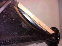
I have just ground the ribs right down - I reckon that gap is 1-2cm.
I am thinking a two part epoxy/putty type compound so I can grind down through the ply, and filler to make the frustrums. Really the top plate will just be to provide a flat surface for the woofer, and the strength will come from the epoxy/filler underneath.
PS - that piece of wood is 20mm thickness and the correct size to sit the woofer on.
Attachments
Last edited:
Looks like £23,21 6FE100 can do job same as SB23NRXS45-8.
Faital Pro :: Faital Pro 6FE100 6" Speaker Driver 100 W 8 Ohm ONLY 23.21
SB23NRXS45-8 needs two 37mm diameter injection ports per driver with 1mm frustum.
6FE100 needs either two 23mm diameter injection ports per driver with 1mm frustum, or with only one port a 32mm diameter.
Data used 6FE100 was 8 liter back box, 0,1 liter front box with 1000Hz resonance.
Attachments
Don't forget to leave room for the surround of the woofer! Thin ply means less room for a cut out for the surround, or is it an inverted surround? I'm guessing not, and seeing the stroke on that baby (x-max) it really can move! Leave plenty of room for that in the mounting area like a routed ring groove for the surround to move in! Better to use a filler shape and frustrum to get the port short but that cone needs to move after all. Just saying, you probably thought of that. I had to mention it, just to be sure ")
Smaller holes in waveguide is less problems for the HF to disrupt it. If it still hits SPL target, would it be a wiser choice?
Smaller holes in waveguide is less problems for the HF to disrupt it. If it still hits SPL target, would it be a wiser choice?
Last edited:
- Home
- Loudspeakers
- Multi-Way
- A Bookshelf Multi-Way Point-Source Horn