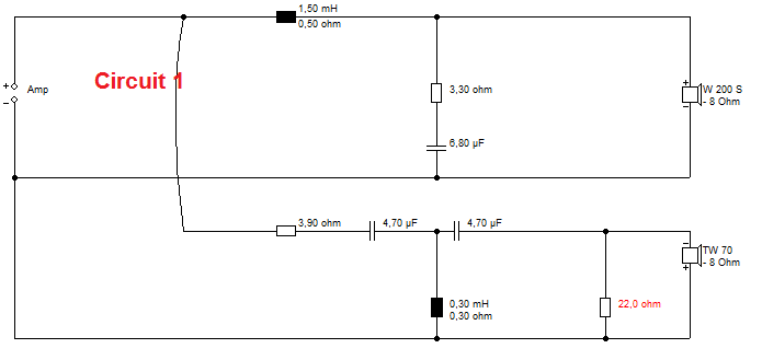
Here's two circuits I used recently on my speakers. Both BW3. Which one do you think sounded smoother and better?
I enclose the equipment on test. Usual Rotel SS amp and CD.
I enclose the equipment on test. Usual Rotel SS amp and CD.
Attachments


Not enough information (isn't it strange, how people tend to think that phase data is not important).
And smoother doesn't mean better. Second one with resistor across the tweeter will of course sound "smoother" which means less "dynamic", which is why I would usually prefer no parallel resistor (even better to move the resistor to the input side of the filter). But this depends on the individual ears. Some people (I think untrained ears) prefer the sound of the "smoother" one.
And smoother doesn't mean better. Second one with resistor across the tweeter will of course sound "smoother" which means less "dynamic", which is why I would usually prefer no parallel resistor (even better to move the resistor to the input side of the filter). But this depends on the individual ears. Some people (I think untrained ears) prefer the sound of the "smoother" one.


Aren't we down to differences which are so small that the room has a much higher impact? At least so in my experience.
But looking at the FR only I would guess that FR1 is "smoothest" FR2 having a bit more "air" to it ....
@Jay .... why do you say: Second one with resistor across the tweeter will of course sound "smoother" which means less "dynamic" ...... why is that so obvious?
But looking at the FR only I would guess that FR1 is "smoothest" FR2 having a bit more "air" to it ....
@Jay .... why do you say: Second one with resistor across the tweeter will of course sound "smoother" which means less "dynamic" ...... why is that so obvious?
But looking at the FR only I would guess that FR1 is "smoothest" FR2 having a bit more "air" to it ....
@Jay .... why do you say: Second one with resistor across the tweeter will of course sound "smoother" which means less "dynamic" ...... why is that so obvious?
My mistake. It is the first circuit that has resistor across tweeter, not the second one. This is usually not my preferred alignment. So we obviously agree with each other...?
I'm not talking from FR (or impedance curve). Only experience. FR doesn't tell me anything.
You can have phase if you want it. I'm not giving anything away at this stage. 🙂
Phase wont tell the difference between the two but it will tell if the speaker is good or not, even tho it is usually not that "accurate".
Strange that a woofer this big has such a high resonance frequency. What is the box tuning frequency? Imo, the bass wont be sufficient, unless it is intended to go with a sub.
I would like to see the graphs of tweeter impedance alone, shaped with the two high-pass filters.
In the absence of that, and with the suspiciously looking impedance peak at 5 kHz in the Circuit 1, I would speculate that Circuit 2 should be better.
In the absence of that, and with the suspiciously looking impedance peak at 5 kHz in the Circuit 1, I would speculate that Circuit 2 should be better.
Last edited:
I'm going to say circuit 1 sounds better, but only because my wife chose circuit 2 first. I think I'm in with a chance.
Well there's not much to choose between them, but its a laugh so I will have a stab at guessing if any circuit is audibly better (without hearing)
I'm going with cct #2. Phase and fr are almost identical, impedance of cct 2 looks nicer. Also I'm not a fan of padding tweeters with a parallel R, an l pad should be better, failing that a single series R. (despite the effect on the Q of the HP filter.
Would I hear ant difference? I simply don't know, probably not I suspect.
Hi,
The circuits are essentially identical, the Q of the highpass is largely
determined by the series 3.9R resistor. The only difference is one
loads the other side of the high pass by 5.3R and the other by 8R,
assuming 7R for the tweeter. I couldn't possibly say one way or the
other, totally depends on the specific drivers and any listener bias.
Given the info, have to go for option 3, very near the same.
rgds, sreten.
Last edited:
Thanks for the interest so far. This is not easy. Here's where it gets interesting. Looking at the important factor. It's not really about the speaker IMO. 😎
Now FWIW, a Solid State feedback amp like the Rotel has a tiny, as small as feasable really, Zobel of 10R and 0.1uF at the output. This is there to stop the amplifier going unstable and into supersonic oscillation when no load, or a difficult load is connected.
Here's two modded Circuit 2's which I think might be an improvement to the sound. Adding little tweaks.
They both have a surprising effect on the overall sound. What it is that they both do at high frequency, say 40kHz? This is the right question IMO.
And you don't need to see the frequency response, impedance or phase to work this out, if you know that inductors and coil drivers become open circuit at high frequency. You just follow the path to ground at HF. 🙂
Attachments


Lol typical system7 curveball...
It probably says more about the amplifier than the speakers, if what you say is accurate.
In that case, it begs the question:
"why treat the symptom and not the cause?"
It probably says more about the amplifier than the speakers, if what you say is accurate.
In that case, it begs the question:
"why treat the symptom and not the cause?"
I haven't yet directly said which circuit sounds better, but one does sound WAY better than the other! I wouldn't worry too much about slight tonal differences. These can be fixed with the treble control. Or a small change in resistor values.I would like to see the graphs of tweeter impedance alone, shaped with the two high-pass filters.
In the absence of that, and with the suspiciously looking impedance peak at 5 kHz in the Circuit 1, I would speculate that Circuit 2 should be better.
Slight ripples in impedance shouldn't be an issue for a solid state amplifier. As it goes, if I wanted a smoother second order type impedance on this third order network and lose the 5kHz peak, I'd just change the filter to a Celestion style 4uF/0.18mH/6uF with 3.3R input resistance. But that would not be my BW3 90 degree phase target, more a LR4 phase aligned idea.
Anyway, here's the Visaton Boxsim tweeter section calculations for the Le 0.16mH Visaton TW70 cone tweeter.
Please don't worry about the fact I'm actually using a Monacor HT-22/8. Just my fancy, because they are similar. I prefer the Monacor's sound.
Attachments


I pitch absolutely straight to my good friends at this forum. No tricks. 🙂Lol typical system7 curveball...
It probably says more about the amplifier than the speakers, if what you say is accurate.
In that case, it begs the question:
"why treat the symptom and not the cause?"
I built a BW3 circuit familiar to me, but by random chance kept it rather simple. It looked good on paper. But it sounded overly bright, splashy, fatigueing. Lots of top end, but EW... not nice to listen to. Lacked that lovely "quietness" and lack of distortion that encourages you to turn it up louder and louder.
I just checked the Rotel RA-931 Amp specs, and it claims:
30 Watts per channel, 20-20kHz, THD < 0.03% into 8 ohms load.
Frequency response 10-100,000Hz +1dB -3dB
TBH, that is probably testing into an big 8 ohm dummy load. It's an op-amp preamp with a regular solid state transistor AB power amp stage.
You think maybe Rotel could make an amp that doesn't exhibit these issues with different loads. They probably could. But it would be less efficient IMO. And wouldn't do so well with really well-designed 8 ohm loads. As it is, they have to design for wildly different 4-16 ohm speakers, and not blow up when no speakers at all are connected. Even just blow a fuse with a short-circuit and take no further damage, which is skilled engineering IMO.
Just for interest, it IS possible to make greatly flat impedance speakers using series crossover methods. Below is our own Cousin Billy's approach. Any amp, SS or valve, is gonna love driving that speaker IMO. 😎
Attachments


Last edited:
Now it is obvious - comparing both tweeter+filter impedance/frequency graphs side by side (post 16), I bet the Cuircit 2 sounds much better. Just see the pronounced impedance knee at the bottom of the Cuircit 1 graph (3 and 5 kHz).I haven't yet directly said which circuit sounds better, but one does sound WAY better than the other!
Measurements DO tells us how the loudspeaker will sound.
Last edited:
Look at again. I'm saying one of these circuits gives the amplifier a better load at supersonic frequencies. And that it matters for a good sound, maybe due to increased SS amplifier stability margin. I may be wrong, but so far all the GOOD circuits I've built do this little thing.

Remember coils and regular drivers go inductive and high at high frequency, so no signal path to ground there. Capacitors (ideally) go to short circuit at high frequency.
So Circuit 1 goes 25.9R (3.9R + 22R) at high frequencies.
And Circuit 2 goes to infinity.
Remember coils and regular drivers go inductive and high at high frequency, so no signal path to ground there. Capacitors (ideally) go to short circuit at high frequency.
So Circuit 1 goes 25.9R (3.9R + 22R) at high frequencies.
And Circuit 2 goes to infinity.
My vote would be circuit 2, with the resistor in series with the tweeter.
(going with my 80/20 experience here - at least 80 % of the time in my experience)
disclaimer: This is usually where actually listening is the best test. 😛
If I ever put a resistor across the tweeter terminals, I usually don't use anything smaller than 25 or 30 ohms or so. Depending on the tweeter, there is a point where too much detail seems to be lost (at least to my ears) if the shunt resistor is too small. Sometimes a 47 ohm across the tweeter takes off just enough of the high freq noise without taking away too much detail overall.
On the other hand, the right amount of series resistor alone can preserve the details.
Again, just my rule of thumb(s), based on what I've observed.
- Status
- Not open for further replies.
- Home
- Loudspeakers
- Multi-Way
- Which crossover sounds better?