Hi Everyone,
Andrew made some comments in another thread about tweeter power and crossover types. I'm sure many of you would expect this, but this was a fun experiment that taught me a lot so I thought I would share.
I used Xsim to see for myself what was going on in terms of the impedance and power dissipated by 1st vs. 2nd order crossovers, specifically resistors in series with the driver.
Of course, I could have easily made some mistakes, or misused XSim or run into a bug I can't see, so I welcome thoughtful and helpful comments here.
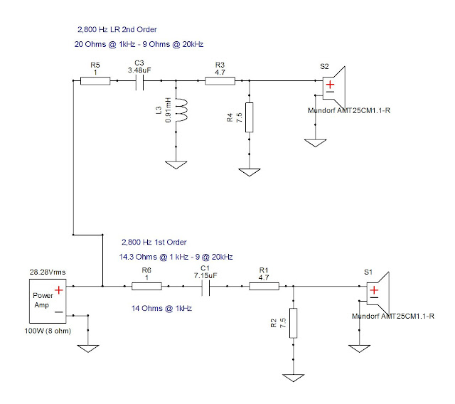
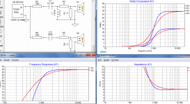
I put together a test schematic, using the same tweeter, which is almost purely resistive. Here's the test circuit. Crossover values are taken straight from the VCap Crossover Calculator online. For both, I entered 8 Ohms as the high pass impedance, which is accurate for the tweeter + padding resistors.
In most cases XSim displayed the data side by side, but for the total circuit impedances I had to export data to a file and add it to get both plots on one chart. To do this graph I increase the impedance of R5 or R6 to get a system impedance graph of one or the other circuit. Please see my findings here:
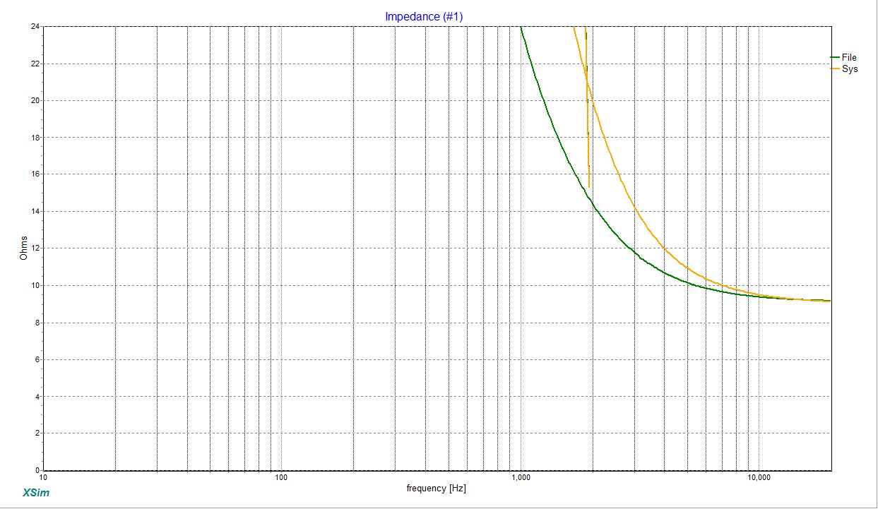 The top, yellow curve is the 2nd order filter, the bottom green line is the first order. As we can see here, the impedance of the 2nd order filter is higher for most of the spectrum.
The original poster also made some comments about resistors in first order design dissipating more power. Thanks to XSim I was able to test resistors in a couple of locations to prove or disprove this theory.
Remember that R1 and R6 are part of the first order , R3 and R5 part of the second order filter.
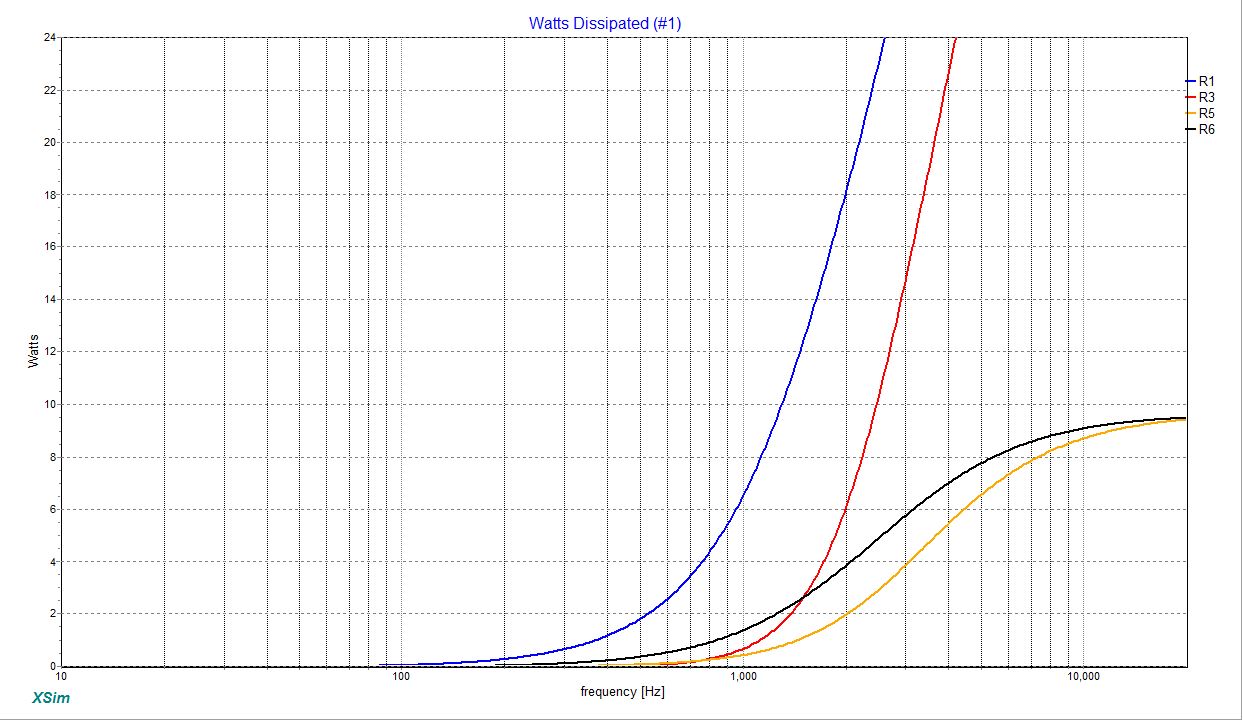
As you can see, regardless of the location of the padding resistor, the power dissipated in the 2nd order is almost always lower than the power dissipated by the 2st order.
Andrew made some comments in another thread about tweeter power and crossover types. I'm sure many of you would expect this, but this was a fun experiment that taught me a lot so I thought I would share.
I used Xsim to see for myself what was going on in terms of the impedance and power dissipated by 1st vs. 2nd order crossovers, specifically resistors in series with the driver.
Of course, I could have easily made some mistakes, or misused XSim or run into a bug I can't see, so I welcome thoughtful and helpful comments here.
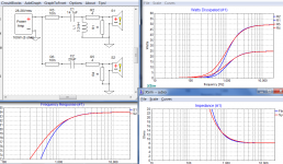
I put together a test schematic, using the same tweeter, which is almost purely resistive. Here's the test circuit. Crossover values are taken straight from the VCap Crossover Calculator online. For both, I entered 8 Ohms as the high pass impedance, which is accurate for the tweeter + padding resistors.
In most cases XSim displayed the data side by side, but for the total circuit impedances I had to export data to a file and add it to get both plots on one chart. To do this graph I increase the impedance of R5 or R6 to get a system impedance graph of one or the other circuit. Please see my findings here:
The original poster also made some comments about resistors in first order design dissipating more power. Thanks to XSim I was able to test resistors in a couple of locations to prove or disprove this theory.
Remember that R1 and R6 are part of the first order , R3 and R5 part of the second order filter.
As you can see, regardless of the location of the padding resistor, the power dissipated in the 2nd order is almost always lower than the power dissipated by the 2st order.
Last edited:
Can you show the relative responses with this as well.
I could but it's probably pooh.
") The goal of this experiment was just to ask about how impedances changed with filters. Not whether the crossovers were optimal for these drivers or not.
The goal of this experiment was just to ask about how impedances changed with filters. Not whether the crossovers were optimal for these drivers or not.Once I would start tweaking the design it gets pretty arbitrary. Also, the first 1 Ohm resistor is not really needed, I put it there just to examine the power dissipation in a resistor in front of the circuit.
Remember, BOTH of the drivers here are the same tweeter.
This isn't a speaker simulation so much as a power experiment. Of course, the red line, below, is the 1st order, the yellow the 2nd order. 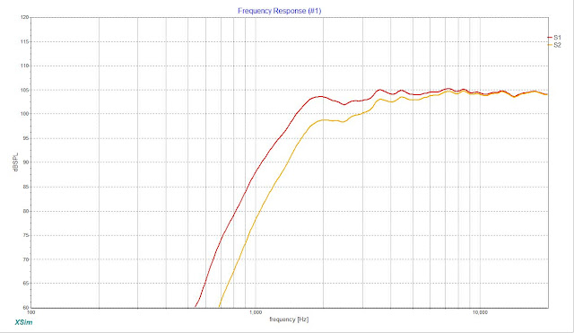
Last edited:
XSin?? Makes it sound like a porno app!
That's why XSin is the paid version.....
I know. Too late to change it!
That's not what I was thinking, you have tried to show two similar filters and I thought that similarity in response would make a better baseline.I could but it's probably pooh.
That's not what I was thinking, you have tried to show two similar filters and I thought that similarity in response would make a better baseline.
Hi Allen,
Nah, I'm comparing 2 different types of filters so that's never going to happen anyway. The "right" high pass filter is dependent on the woofer anyway, and the woofer's high pass filter will need to be adjusted... you see the can of worms that gets me into?
I just wanted to keep it simple to show that in general, a second order filter has a higher impedance and hope that anyone reading this will understand that "Your Mileage May Vary depending on specific driving conditions...."
Since the original poster made a general statement about which has a higher impedance, and which needs bigger (higher power) resistors a general answer is good enough.
If you'd like, you could whip something up with XSim along your lines of thinking and post your findings. Takes mere minutes.
Best,
Erik
Last edited:
Sure, why not.
Bill. 20 minutes in, so far so good. Maybe the quoted issue is a job for the delta capability. I don't see a ReadMe in the program folder.. I'll try to work it out.
Bill. 20 minutes in, so far so good. Maybe the quoted issue is a job for the delta capability. I don't see a ReadMe in the program folder.. I'll try to work it out.
In most cases XSim displayed the data side by side, but for the total circuit impedances I had to export data to a file and add it to get both plots on one chart. To do this graph I increase the impedance of R5 or R6 to get a system impedance graph of one or the other circuit.
Last edited:
XSin?? Makes it sound like a porno app!
 Fixed the title.
@Erik.
For the first (workaround) resistors I would use 0.01 instead of 1 to exclude their effect.
Although I can't upload the screenshots you'll find that with all other things equal, adjusting the capacitor in the first order filter to bring the response in to line at some given frequency should lead you to comparable power dissipation at that frequency.
So far..
Response is ~ the same above 6k, so is power and impedance.
Error: Cannot upload images. Tried both export to png through the program, also export to clipboard. Seems to be the site, will report to mods.
As far as I know, you have to host your images somewhere else, this site doesn't allow images to be uploaded. If so, someone please tell me how!
Erik
@Erik.
For the first (workaround) resistors I would use 0.01 instead of 1 to exclude their effect.
Again, that wasn't the test I wanted to run. I wanted those resistors in no matter what. I might as well see all of them at once. My work around was to get the system impedance, so I would set the first R to a value of 1000 or more for EITHER the 1st or 2nd order design. This allowed me to plot the system impedance of the system that did NOT have the elevated R.
@Erik.
Although I can't upload the screenshots you'll find that with all other things equal, adjusting the capacitor in the first order filter to bring the response in to line at some given frequency should lead you to comparable power dissipation at that frequency.
Yeah, but who designs like that? I mean, you pick a crossover frequency and then your values. You don't design a 1st order graph to look like a 2nd order graph.
Again, not how I wanted to run a test. Of course, above the cut off frequency everything will normalize. Again, not the test. Some one made a general statement that 1st order filters would require higher wattage resistors, and I have no evidence of that in this design, it sounds like you didn't either.
Best,
Erik
Noooooooo!!!! How am I going to get any readers now??
Fair enough.Again, that wasn't the test I wanted to run. I wanted those resistors in no matter what.
I realise this.My work around was to get the system impedance, so I would set the first R to a value of 1000 or more for EITHER the 1st or 2nd order design. This allowed me to plot the system impedance of the system that did NOT have the elevated R.
No-one. The point was to equalise the test. Comparing a 1st and 2nd order filter is apples to oranges so you need to think outside the box, define a point to all this, and target that to prove it.Yeah, but who designs like that?
No, I don't recall claiming so.Some one made a general statement that 1st order filters would require higher wattage resistors, and I have no evidence of that in this design, it sounds like you didn't either.
Hi alan,
We are seeing different oranges. The orange for me was the crossover frequency. I'm not sure what you are calling an orange.
Using a fixed crossover frequency to me seems more like comparing the same oranges. You seem to be trying for same response, those are your oranges and you can use them if you'd like.
No, you are not the one who made any claims about power and filter orders.
It sounds to me like you are making a different point than I was, and you are free to do so, just don't play with my oranges. Hope your pics get uploaded.
Best,
Erik
Good-o. Here're a couple of filters, each has an f3 of 1000Hz.It sounds to me like you are making a different point than I was, and you are free to do so, just don't play with my oranges. Hope your pics get uploaded.
AndrewT makes the following points..
How do you like them apples?A first order filter to the tweeter has a higher impedance to present to the amplifier/Source.
Adding in a second pole LOWERS the impedance presented to the Source.
That means MORE current flows and more heat is generated in the dropping resistor.
Attachments
- Status
- This old topic is closed. If you want to reopen this topic, contact a moderator using the "Report Post" button.
- Home
- Loudspeakers
- Multi-Way
- XSim : Impedance and Power in 1st vs. 2nd Order Filters