I installed REW. What gate length should I be using? Left Side, Right Side? Is the default "Tukey 0.25" appropriate?
In terms of setup, is this ok?
- Pull the enclosures to the middle of the room.
- Have the bottom one sitting 2" above floor (like I intend to use them) and the top enclosure sitting atop to reproduce how the baffle would behave
- Place the mic at ear-level
- How far away should I place the mic from the drivers?
You set the window by looking at the IR and setting it so you have windowed out the reflected content. However with the driver near the floor then this will be v early on indeed. I am not sure how well that will work. Is your intent just to include the effect of the boundary in the response?
Is the OP using a gated response? That curve looks like combing effect from 2 woofers with near field mic, and too big a box.
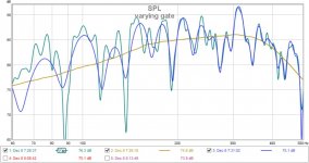
So I installed REW and made a couple measurements with varying gates to get a flavor of how it looks:
- Greenish curve is with 500ms gate, 1/48 smoothing
- Blue is 50ms, unsmoothed
- Golden is 5ms, unsmoothed
According to the White Paper by Bagby pointed earlier, a 5ms gate is good for measurements down to 200Hz, so useless for my application.
A 50ms would be good down to 20Hz, more than enough.
What do more experienced eyes see here?
Attachments
You know, I have had a chance to think about this:
If you are checking frequency response in a simple unfilled/unstuffed box
(with thin walls?) then you are simply checking what the box does.
In my view, you are better off checking the response from an installation that is much, much closer to what your final application will be.
I.E. sealed, in 1/2 a cubic foot, filled with acoustic absorbent of your choice.
I recommend unfaced pink panther.
Hey Scott!
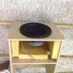
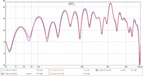
0.5 cu.ft = 14 liter. I went ahead and resized the box to 20 liter and added stuffing. Glass fiber panels I had laying around. Attached is a picture. The added panels take 10 liters, or they would take that much if they were solid.
I measured with 50ms gate and compared stuffed (red) vs. unstuffed (blue).
What do you think?
Attachments
if you want to use an in room measurement to examine the LF response then I would consider using FDW instead.
That is frequency dependant windowing in REW, right? Which setting would you recommend?
yes REW has it now or you can use acourate which gives greater control over exactly how the window is specified. There isn't really a right value, trial and error might be the way forward. I would start at 6 cycles and go from there.That is frequency dependant windowing in REW, right? Which setting would you recommend?
Ultimately the measurement is going to be contaminated by the floor reflection, I think you'll get better data if lift it up in the air (albeit depends how big your room is and/or what the weather is like, it's not exactly the time of year for this kind of work!)
From the feedback above it seems my testing approach was flawed: the walls too thin, the edges too sharp, and the back panel too close to the driver. So back to the drawing board.
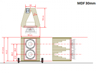
Below is a drawing of what I envision. Each enclosure is 11 liter, minus 3 liter for the driver that's 8 liter. Such a Vb with "heavy filling" (UniBox) implies Qtc of 0.65 or 0.72 with "walls covered".
Front panel is 50cm wide (230Hz baffle step F3), with 3in radiused edges. The enclosure would be translam, allowing for very thick walls and non-parallel surfaces. Hopefully resonances are pushed above 500Hz, and back wave is minimized.
There is an opening to house the Hypex UcD amp in there. Not drawn, but planned are some 1" diameter vertical holes across the translam to hold sand for damping purposes. Not sure damping is needed at these frequencies, though. Stiffness needed for sure.
FWIW, the red front panel is 40mm Micarta, and the top and bottom covers are likely plywood or some wood meant to show nicer finish.
This prototype will be a lot more expensive to build, and time-consuming. Would very much appreciate feedback!
Attachments
This prototype will be a lot more expensive to build, and time-consuming. Would very much appreciate feedback!
I normally spend more money on speakers and a smaller percentage of the budget on cabinets.
You could re-group and create plans for a low cost second effort on measurements. Knowledge and skills needed for perfecting any speaker.
You probably still have enough MDF to build a robust measurement cabinet with thick panels, clever cross bracing, and attention to edge diffraction for additional testing before spending the big-bucks on Baltic Birch panels or 200-pound MDF TransLam stack-ups. If you have a 0.5" router, you can put a 1.5" edge radius on your measurement cabinet....maybe....before and after measurements.
I glue 0.75" MDF to 0.75" Baltic Birch for the cabinet panels, and engineer interlocking cross bracing which divides the rear air volume plus shock-supports the woofer magnets. Local cabinet shop shaper cuts a 3" radius on the stacked front baffle. Shaped black baffle, flat Baltic Birch side panels. No veneer skills.
There are clever translam examples on the forum which describe details which best leverage this expensive technology.
I suspect the huge dips in the FR which are room induced cancellations will remain regardless of enclosure shortcomings. It's important to consider your response below 150hz will be quite different once the rhythmic subs are included with a 2nd order LP filter.
If you want to 'see' the driver, enclosure and alignment you'll have to take these outside and measure high off the ground eliminating all boundaries within the gate window. Only then will you get the naked truth. Not sure what the value would be in that as you won't be listening to them that way but..............
I'd add in the Rythmiks and measure the 400hz and below response as a system simply because all of it is within the modal region and the only valid adjustments here will be placement and eQ.
testing results
I promised Mr. Lewinsky that I would do some real world measurements of a
Goldwood 10inch pro woofer that I happened to have on hand.
http://www.parts-express.com/pedocs/specs/290-395-goldwood-gw-10120-specifications.pdf
So, I thought why not post them here ? I have no idea how they will compare to a sim.
In a one cubic foot sealed enclosure, pointing upwards towards an 8 foot ceiling,
11 inches away from one side boundary and 41 inches below the ceiling.
600Hz 117db
500 121
400 114
300 115
200 114
100 112
90 111
80 110
70 109
60 108
50 105
40 104
35 103
30 100
Of special note: this was actual SPL's in the very near field, one inch away from the cone. sinewaves. yep drove me crazy, but I promised a real world test.
test box
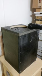
Here is a picture of the "test box"
It is 12x12x17 external dimensions, 3/4 inch mdf.
As fate would have it, an audiophile friend stopped by and I asked him to listen as I swept sine waves down in frequency, and asked him to tell me when he thought the output level has diminished to the point of uselessness.
He say, okay there ! (at 36 Hz)
Next we tested the resonant frequency. It was 67Hz. The enclosure is right at
one cubic foot. For pro sound drivers, the required box volume is larger than what simulators will predict. The enclosure was filled up completely with a mixture of daycron and pink panther. I can't imagine the Beyma drivers would be a whole lot different, after all compare the specs. I sent the Beyma info to a friend of mine who is also a math professor and also builds drivers for
automotive (pro sound) competitions. His living room is stacked chock full of trophies from winning first place in these competitions. I asked him what size box for the 10G40's and he said at least 3/4 a cubic foot, and maybe even as much as one cubic foot,but DO NOT place it in a small box because of the back wave reflections. He is 71 years old. He is also who I call when I have questions about speaker design.
Attachments
Here is a picture of the "test box"
It is 12x12x17 external dimensions, 3/4 inch mdf.
As fate would have it, an audiophile friend stopped by and I asked him to listen as I swept sine waves down in frequency, and asked him to tell me when he thought the output level has diminished to the point of uselessness.
He say, okay there ! (at 36 Hz)
Next we tested the resonant frequency. It was 67Hz. The enclosure is right at
one cubic foot. For pro sound drivers, the required box volume is larger than what simulators will predict. The enclosure was filled up completely with a mixture of daycron and pink panther. I can't imagine the Beyma drivers would be a whole lot different, after all compare the specs. I sent the Beyma info to a friend of mine who is also a math professor and also builds drivers for
automotive (pro sound) competitions. His living room is stacked chock full of trophies from winning first place in these competitions. I asked him what size box for the 10G40's and he said at least 3/4 a cubic foot, and maybe even as much as one cubic foot,but DO NOT place it in a small box because of the back wave reflections. He is 71 years old. He is also who I call when I have questions about speaker design.
Hey Scott. Thanks for taking the time to do that!
Could you please be more specific about what/how you asked the guru regarding the 10G40?
Was his answer in the context of 80-500Hz sealed cabinet operation? Active crossover?
The comment about back wave reflection...I tend to think he was assuming a rectangular box, wasn't he? I also tend to think the shape I drew in the drawing posted above would minimize back wave reflections (BTW, my plan is to place significant fiberglass and batting at the tip of the triangular chamber).
FWIW, 3/4 cubic foot is about 20 liters, which represents Qtc of 0.5.
It's all about the (faulty?) sims
It was a conversation on the telephone. He just happened to call while I had the 10G40 spec page pulled up on-line. I read off the pertinent specs and asked him for a estimated volume. The whole point I am trying to make here, is that SIMS do not predict the real world. A few posts above here, in this thread, or perhaps in another, a poster recommended building another test box before you spend myriads of time and money with an esoteric enclosure that might, in the end, prove unsatisfactory. Lord knows it has happened to me. About 25 years ago, I tried to duplicate the Wilson Puppy enclosure using layers upon layers of mdf. It was so dead that there was no "life" in the music. Somebody shared the link below,in another thread. You might find it interesting !
Tuning cabinet vibrations in a real world speaker Fink Audio-Consulting
Hey Scott. Thanks for taking the time to do that!
Could you please be more specific about what/how you asked the guru regarding the 10G40?
Was his answer in the context of 80-500Hz sealed cabinet operation? Active crossover?
The comment about back wave reflection...I tend to think he was assuming a rectangular box, wasn't he? I also tend to think the shape I drew in the drawing posted above would minimize back wave reflections (BTW, my plan is to place significant fiberglass and batting at the tip of the triangular chamber).
FWIW, 3/4 cubic foot is about 20 liters, which represents Qtc of 0.5.
It was a conversation on the telephone. He just happened to call while I had the 10G40 spec page pulled up on-line. I read off the pertinent specs and asked him for a estimated volume. The whole point I am trying to make here, is that SIMS do not predict the real world. A few posts above here, in this thread, or perhaps in another, a poster recommended building another test box before you spend myriads of time and money with an esoteric enclosure that might, in the end, prove unsatisfactory. Lord knows it has happened to me. About 25 years ago, I tried to duplicate the Wilson Puppy enclosure using layers upon layers of mdf. It was so dead that there was no "life" in the music. Somebody shared the link below,in another thread. You might find it interesting !
Tuning cabinet vibrations in a real world speaker Fink Audio-Consulting
OK. Point taken.
So back to the above points, also by LineSource and mayhem13.
Regrouping:
- Front panel: I can add another layer to the front panel. I could either glue a 12mm MDF panel to the existing one, or sandwich MDF-rubber sheet-MDF using screws from MDF to MDF. The rubber sheet is the limp, sound absoption rubber used on walls, 3mm thick. Which approach do you deem best?
- Rounded edges: That would be a 40cm wide panel (existing box). I can add half cylinders made from 4" PVC pipes along the vertical edges to emulate the drawing above.
- Back-panel reflection: I'll also take off the top cover, cut it narrower, and glue it on a downwards slopes (so to make for a triangular vertical cross-section)
Merry Christmas, BTW!
OK. Point taken.
So back to the above points, also by LineSource and mayhem13.
Regrouping:
- Front panel: I can add another layer to the front panel. I could either glue a 12mm MDF panel to the existing one, or sandwich MDF-rubber sheet-MDF using screws from MDF to MDF. The rubber sheet is the limp, sound absoption rubber used on walls, 3mm thick. Which approach do you deem best?
- Rounded edges: That would be a 40cm wide panel (existing box). I can add half cylinders made from 4" PVC pipes along the vertical edges to emulate the drawing above.
What do you think?
- Back-panel reflection: I'll also take off the top cover, cut it narrower, and glue it on a downwards slopes (so to make for a triangular vertical cross-section)
Merry Christmas, BTW!
And Merry Christmas to you and yours as well
")
I'd say to get rid of all that thin wood. Sure, make the baffle board as strong as you see fit. Fill the test box with acoustic absorbent material. The test box should be very rigid and air tight. Radiused edges, if your upper most frequency to be covered is 500Hz, will have very little effect
Cabinet construction
Hi Guys,
Merry Christmas to everyone!
Kids going crazy as we are about to open presents.....!
Anyway just a quick post on some general cabinet construction;
Good old heavy birch plywood 24mm front baffle and the rest 18mm is the best all round solution.
Stranded ( not block board) Bamboo plywood (grass not wood actually)is even better but expensive.
I glue get all my cabinets CNC'd with mitred edges and glued & screw all joins....Large gauge "Turbo" wood screws (sold in B&Q in UK) allow massive torque to be applied. internal panel dampening and energy conversion.
Fist I apply 3 layers of 3mm thick,(so 9mm in total) of self adhesive Jiffy Envoy Multi underfloor insulation to each internal surface.
Next I "Pyramid" shapes of 9mm thick fibre board to create an uneven series of peaks and valleys on all opposite surfaces.
Lastly I mix both "Twaron" and loft insulation inside soft cotton stocking sleeves and hot melt glue it in a central position.
I use flexible silicone adhesive for driver gaskets, and 1mm thick black felt for surrounds and baffle cosmetics.
Lastly, an important point on cabinet depth....
Best to make front to back depth of cabinets very shallow or very deep....In between is the worst....
Very shallow (assume 10cm) has the benefit that the first reflection off the internal face of the rear baffle is only almost instantaneous ie only two 33,000's of a second ie 20cm travel at 330 meters per second.
Current thinking in audiologists circles is that most people can detect time
differentials down to around 40 to 50 micro second (40 to 50 one millionth of a second) and start to register 100 microsecond delays as clearly detectable.
When it comes to voices / music / sound reproduction the longer the delays the more objectionable or "un-natural" the result. Until you get up to around one half of a second or longer where most people are able to easily separate out the echoes....
Hope this helps.....Must dash, got presents to open!
Cheers
D.
Back at it!
So I'm back at designing my midbass section. Constraints haven't changed: 4-way active system using digital crossovers, linear phase, time-aligned. The bottom end will be handled by two Rythmik 12" in DIY sealed enclosures. The midbass will be handled by two 10G40 per side in their own sealed boxes, playing from 60-80Hz to somewehere in the 350-500Hz range.
Midbass baffle width I'm thinking 40cm for a baffle step at 290Hz. However I'm considering 2" or 3" roundings at the corners so baffle would need to be wider.
I want to use 40mm-thick Micarta for the front baffle. Micarta is strong, rigid, and absorbs vibration very well. The front plate will be very heavy too.
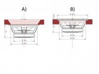
I'm wondering If I would be better off mounting the drivers like in A) or B) in the attached image, that shows a cross-section of the front baffle where the light colored portraits the cutout.
A) would allow better air flow I think, at the expense of being more difficult to do, while B) would provide a more rigid front baffle and more material for the screws to grab onto.
Opinions please?
So I'm back at designing my midbass section. Constraints haven't changed: 4-way active system using digital crossovers, linear phase, time-aligned. The bottom end will be handled by two Rythmik 12" in DIY sealed enclosures. The midbass will be handled by two 10G40 per side in their own sealed boxes, playing from 60-80Hz to somewehere in the 350-500Hz range.
Midbass baffle width I'm thinking 40cm for a baffle step at 290Hz. However I'm considering 2" or 3" roundings at the corners so baffle would need to be wider.
I want to use 40mm-thick Micarta for the front baffle. Micarta is strong, rigid, and absorbs vibration very well. The front plate will be very heavy too.
I'm wondering If I would be better off mounting the drivers like in A) or B) in the attached image, that shows a cross-section of the front baffle where the light colored portraits the cutout.
A) would allow better air flow I think, at the expense of being more difficult to do, while B) would provide a more rigid front baffle and more material for the screws to grab onto.
Opinions please?
Attachments
So I'm back at designing my midbass section. Constraints haven't changed: 4-way active system using digital crossovers, linear phase, time-aligned. The bottom end will be handled by two Rythmik 12" in DIY sealed enclosures. The midbass will be handled by two 10G40 per side in their own sealed boxes, playing from 60-80Hz to somewehere in the 350-500Hz range.
Midbass baffle width I'm thinking 40cm for a baffle step at 290Hz. However I'm considering 2" or 3" roundings at the corners so baffle would need to be wider.
I want to use 40mm-thick Micarta for the front baffle. Micarta is strong, rigid, and absorbs vibration very well. The front plate will be very heavy too.
I'm wondering If I would be better off mounting the drivers like in A) or B) in the attached image, that shows a cross-section of the front baffle where the light colored portraits the cutout.
A) would allow better air flow I think, at the expense of being more difficult to do, while B) would provide a more rigid front baffle and more material for the screws to grab onto.
Opinions please?
I would use "B" except that I would also chamfer the corners off, that are closest to the basket spokes. The degree of chamfer would be derived, by determining the amount of "grip" your mounting bolts need.
Also, pay close attention to the details about cabinet construction, that Derek so graciously offered. The driver mounting plate needs to be both very stiff, and very well damped.
- Status
- This old topic is closed. If you want to reopen this topic, contact a moderator using the "Report Post" button.
- Home
- Loudspeakers
- Multi-Way
- Midbass section design with Beyma 10G40