Well, at least you're using them in horns!
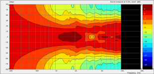
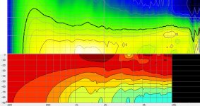
Back to the regularly scheduled programming..........here's an IB sim of my wg. This looks much better on the low end though the IB shows it wider which is to be expected. The second plot is a comparison of Geddes' PolarMap and the VACS contour - PolarMap on top.
Back to the regularly scheduled programming..........here's an IB sim of my wg. This looks much better on the low end though the IB shows it wider which is to be expected. The second plot is a comparison of Geddes' PolarMap and the VACS contour - PolarMap on top.
Attachments
A quick question to Dr Geddes and Nate,
A small question on the contour map in post 202
I see that the usual -6dB line (and lower) is very much close to constant directivity
But the 0 dB line isn't. It has narrowing between 500Hz to 4000Hz.
Similarly -3dB line is somewhere in between.
My question is what changes in waveguide (not EQ etc) will be needed such that all lines (higher than -6dB) will be flat and hence constant directivity.
This can be seen in many polars, the above one I took just as an example...
Absolutely! You get what you research, you no longer get what you pay for.It is a lot like buying a purse - its the fashion that sets the price, not the performance.
Has anyone tried the Selenium D250x as a mid driver in a Synergy?
http://www.parts-express.com/pedocs/specs/264-204--d250-x-spec-sheet.pdf
the specs and response graphs look very encouraging as is the cost.
http://www.parts-express.com/pedocs/specs/264-204--d250-x-spec-sheet.pdf
the specs and response graphs look very encouraging as is the cost.
Thinking about it some more I'm not sure I understand what you're saying there........could you explain it in a different way?
If the sim is infinite baffle then that is the answer, but I thought that you had to change the model to make it work right. Is it still infinite baffle, just that the baffle has moved back?
A quick question to Dr Geddes and Nate,
A small question on the contour map in post 202
I see that the usual -6dB line (and lower) is very much close to constant directivity
But the 0 dB line isn't. It has narrowing between 500Hz to 4000Hz.
Similarly -3dB line is somewhere in between.
My question is what changes in waveguide (not EQ etc) will be needed such that all lines (higher than -6dB) will be flat and hence constant directivity.
This can be seen in many polars, the above one I took just as an example...
The larger the waveguide and the more rounded the mouth edge is, the smoother the response will be in the center. Its all about the mouth edge diffraction - hard to eliminate completely.
The larger the waveguide and the more rounded the mouth edge is, the smoother the response will be in the center. Its all about the mouth edge diffraction - hard to eliminate completely.
Ok. Thanks!
Ahh ok then I do get it.If the sim is infinite baffle then that is the answer, but I thought that you had to change the model to make it work right. Is it still infinite baffle, just that the baffle has moved back?
That sim was infinite baffle with the mouth roundover tangent to the IB so not freestanding at all.
The SEOS has excellent horizontal polars as well. Could this be due to the high aspect ratio of the mouth (width to height) making the diffraction more random? Obviously the shape takes care of the "axial issue", but it seems to do really well in taking care of the issues I see around 7khz in a lot of these waveguides as well. They also have a variable mouth radius. I personally wouldn't want to go that small in the vertical but the horizontal polars can't be beat IMO.The larger the waveguide and the more rounded the mouth edge is, the smoother the response will be in the center. Its all about the mouth edge diffraction - hard to eliminate completely.
Hi Dr. Geddes:
Take a rectangular/pyramidal horn as often used in DIY synergy horns. If that is a pig compared to an EOS waveguide, what kind of lips would you recommend be put on it to combat mouth diffraction?
Given that size is the dominant challenge in horns, I like to convert from a hard wall to a lossy edge- by using acoustic foam (higher loss than the reticulated stuff used IN Geddes OSWGs) around the edges, even projecting forward/extending the profile, much of the "job" can be done with less physical space.
Peavey used something like this in their quadratic throat wg, there's some contention about IP on that design but that's not relevant here. I've used it to great effect to extend the flare on the JBL WG used in the Econowave designs, as well as on my pseudo-oswg guides.
Ahh ok then I do get it.
That sim was infinite baffle with the mouth roundover tangent to the IB so not freestanding at all.
Got it - not what was shown with a free standing waveguide.
The SEOS has excellent horizontal polars as well. Could this be due to the high aspect ratio of the mouth (width to height) making the diffraction more random? Obviously the shape takes care of the "axial issue", but it seems to do really well in taking care of the issues I see around 7khz in a lot of these waveguides as well. They also have a variable mouth radius. I personally wouldn't want to go that small in the vertical but the horizontal polars can't be beat IMO.
The SEOS that I measured was good, but certainly not "polars can't be beat." I am not sure that there are a lot of the highly detailed polars like you and I have for our devices. I suspect that when compared one to one in the PolarMap program they would not come out on top. Also, the SEOS that I have seen have been very wide. The narrower the pattern, the harder it is to control.
Given that size is the dominant challenge in horns, I like to convert from a hard wall to a lossy edge- by using acoustic foam (higher loss than the reticulated stuff used IN Geddes OSWGs) around the edges, even projecting forward/extending the profile, much of the "job" can be done with less physical space.
Yes, I can see that absorption could be used to the same effect as a large radius, maybe even in a smaller space (although that is not obvious to me.) I am not sure what you mean by the difference between Acoustic Foam and reticulated foam. There are only two types of foam; open cell and closed cell, but both come in a wide range of pore sizes. Closed cell is not so good at absorption because the waves cannot penetrate into it. My foam is very large pore open cell for minimum absorption, but a much smaller cell size makes it much more absorptive. What would be best is a gradation of cells from large to small, but this cannot be done in a single block, it would take layering.
Any means of diminishing the mouth edge effects is good. In sharp edge square devices the diffraction is spread so wide that it does not have a strong far field effect, but it does still reflect the wave back down the horn creating a series of standing waves which can be seen in the plots.
A highly coherent waveguide like the OS or Nate's will have a pronounce effect from the mouth, but minimal standing waves and hence and overall smoother power response.
Oh wow, thanks for the offer! For coordinates do you want what I input into AD for the baffle (wg)? It would be interesting to compare and might get me started on the right foot. That said, if I can get AD to reasonably match my measured result then I may just stick with AD. I'll probably build a large elliptical Synergy but I can do a little "eye interpolation" for that as far as the axisymmetric sim goes. Mostly I want to investigate different mouth treatments.
I tried your workaround for extending the wg, but AD kept saying "Solver Aborted" right after I start it. Let me make sure I understand.........you're saying to have a straight duct extension between the diaphragm and the actual wg? Rather than go 10m I went 10' and then added another 10' for the VACS pressure contour setting. I tried several times and it keeps saying aborted. To get a baseline I'm now running the sim with the mouth roundover tangent to the IB. That's running just fine.
Hi Nate,
I'm sorry, I didn't explain it well enough.
Enter this in your axidriver coordinates ("baffles" tab) with nothing else added, and a dome of 1 inch to see what I mean;
.2 .2
.4 .1
.025 -10
This will create a very basic waveguide in "semi free-field" conditions.
This sets the infinite baffle layer 10m behind the diaphragm so there still is the reflection only it is of less disturbance. You could of course make it more accurate where the outside of the waveguide is, but I kept it simple.
Of course this is sub-optimal and true free field would be more accurate.
In AxiDriver, you can't go further than +-90deg for directivity plots but of course you want this data to.
Besides this, I just tested this example in AxiDriver, which I havent touched in a long time. It was shocking to notice how sloooow it is compared to ABEC. (basically because of the lack of multithreading)
These are the same sort of coordinates I would need to setup an ABEC project for you.
If you have or can make this data, I would like to have the contour in 100 steps.
If this is too fine for you to create, 10 steps will also do, but 100 is better, especially for future progress.
Once you start using ABEC coupled with LEM (the akabak part), you'll never look back (and probably dismiss basically all other design software that you use). It is quite a leaarning curve, but I guarantee you that i t will be worth it.
grtz Kees
Last edited:
- Status
- This old topic is closed. If you want to reopen this topic, contact a moderator using the "Report Post" button.
- Home
- Loudspeakers
- Multi-Way
- Mini-Synergy Horn Experiment