Hi Folks,
About a year ago I begin to think about modifying an old pair of Urei 809 speakers that I bought new almost twenty years ago. At that time they were very highly regarded as Studio Monitors and you could see them used in many professional studios (and even today). They were popular and not expensive. (About U$ 1300-1500). They had a big brother (813), which was better.
In January ‘03 I bought a pair of Genelec 1030 active biamped monitors, and I vas shocked by the difference in sound. What I heard was more high-end extension. uncolored mids, very tight and controlled bass, outstanding soundstage and way more definition (this is as long as you do not abuse them producing high SPLs, After all they have a 6.5 woofer)
The difference in sound was that big ( they are used in the same room) that I thought about selling the old Ureis or perhaps do something on them to improve the sound.
What follows is the explanation of what I did. I'm not a speaker designer (I do sound design and mixing for TV/movies for a living) so my first action was gather as much information as I could. I read about speakers and crossover as much as possible and then I asked a few questions in this Forum which produced some very useful suggestions. And here I am now with a pair of modified Urei that I really like.
The original speaker:
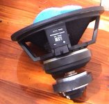
The basic design -as you can see in the pictures attached- is a coaxial design in a small/mid ported speaker enclosure. The woofer is a 12" unit and there's a distinctive blue horn for the mid/high range. You can notice that the horn fires from the back of the woofer. Woofer and horn moving coils distance is about 9 cm.
About a year ago I begin to think about modifying an old pair of Urei 809 speakers that I bought new almost twenty years ago. At that time they were very highly regarded as Studio Monitors and you could see them used in many professional studios (and even today). They were popular and not expensive. (About U$ 1300-1500). They had a big brother (813), which was better.
In January ‘03 I bought a pair of Genelec 1030 active biamped monitors, and I vas shocked by the difference in sound. What I heard was more high-end extension. uncolored mids, very tight and controlled bass, outstanding soundstage and way more definition (this is as long as you do not abuse them producing high SPLs, After all they have a 6.5 woofer)
The difference in sound was that big ( they are used in the same room) that I thought about selling the old Ureis or perhaps do something on them to improve the sound.
What follows is the explanation of what I did. I'm not a speaker designer (I do sound design and mixing for TV/movies for a living) so my first action was gather as much information as I could. I read about speakers and crossover as much as possible and then I asked a few questions in this Forum which produced some very useful suggestions. And here I am now with a pair of modified Urei that I really like.
The original speaker:
The basic design -as you can see in the pictures attached- is a coaxial design in a small/mid ported speaker enclosure. The woofer is a 12" unit and there's a distinctive blue horn for the mid/high range. You can notice that the horn fires from the back of the woofer. Woofer and horn moving coils distance is about 9 cm.
Attachments
Passive crossover
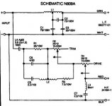
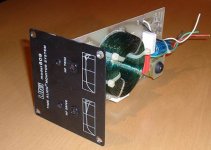
They use a passive somehow complex crossover-see picture- that people liked to modify with different degrees of success. The crossover point is around 1.5 K with a couple of controls in a plate located at the front of the speaker. The selling point of this model was that Urei claimed they were "time aligned".
They use a passive somehow complex crossover-see picture- that people liked to modify with different degrees of success. The crossover point is around 1.5 K with a couple of controls in a plate located at the front of the speaker. The selling point of this model was that Urei claimed they were "time aligned".
Attachments
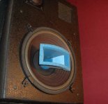
More photo details
The election of the amplifier for these speakers was said to be very critical. The recommended amp was a Bryston (do not remember the model) but at that time I didn't have the money to buy it so I ended up getting a JBL 6260 amp. (300w/ch/ 4ohm.) What I liked about this amp was the absence of a fan and the massive heatsinks. The sound from this combination was never great. I tried other brands/models but never got "the sound".
I used these speakers all those years as a mid/far field monitor in a medium sized Post-production mixing room. There was no abuse but over the years the woofer's foam surrounds were disintegrating so last year the local JBL representative fixed them and the horn's voce coils where also inspected.
So this was the original situation. Next post: The MODs
Attachments
MODs-Part 1
The work covered basically three points:
Upgrade the high freq range.
New active crossover
New amplification
Upgrading the high frequency range:
The frequency vs. power plot of the horn's response shows that it begins to go down at 8 K with little output beyond 15K. I first it was tried to eq the horn but got little improvement so I considered adding a tweeter. At that time I was reading great reviews about Scan-Speak tweeters, so I asked here in this forum about how a SS tweeter would integrate. It was "kindly" suggested to consider another kind of tweeter: the Fostex FT17. This is an inexpensive model praised for its sound and value. That was good news. This Fostex driver cost 1/4 the price of the SS unit. So 3 of them were ordered without even listening to the unit.
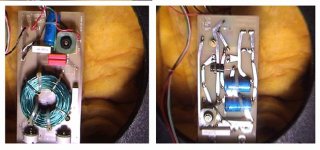
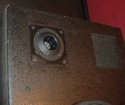
Now, where to install the tweeter? The old passive crossover is mounted with a square metal front plate to the front of the speaker. It is exactly the size of the tweeter and is located asymmetrically from the left/right sides of the enclosure. So it was as easy as pop out the crossover and build a little MDF piece -a square piece with a round cut in the middle- to mount the tweeter. To attach it to the enclosure, the same holes holding the crossover plate were used-see picture. Some silicone caulking finished the installation.
The work covered basically three points:
Upgrade the high freq range.
New active crossover
New amplification
Upgrading the high frequency range:
The frequency vs. power plot of the horn's response shows that it begins to go down at 8 K with little output beyond 15K. I first it was tried to eq the horn but got little improvement so I considered adding a tweeter. At that time I was reading great reviews about Scan-Speak tweeters, so I asked here in this forum about how a SS tweeter would integrate. It was "kindly" suggested to consider another kind of tweeter: the Fostex FT17. This is an inexpensive model praised for its sound and value. That was good news. This Fostex driver cost 1/4 the price of the SS unit. So 3 of them were ordered without even listening to the unit.
Now, where to install the tweeter? The old passive crossover is mounted with a square metal front plate to the front of the speaker. It is exactly the size of the tweeter and is located asymmetrically from the left/right sides of the enclosure. So it was as easy as pop out the crossover and build a little MDF piece -a square piece with a round cut in the middle- to mount the tweeter. To attach it to the enclosure, the same holes holding the crossover plate were used-see picture. Some silicone caulking finished the installation.
Attachments
Upgrading the crossover: As the speaker is going to be tri-amped, the old passive crossover must go away. As the woofer/horn/new tweeter combination is not aligned in time by itself, this speaker is an excellent candidate for an active digital crossover. The required unit should have very flexible filters, MUST have delay units per driver band and some equalizers. The Behringer Ultradrive 2496 is an inexpensive device that has all the processing needed. It has 3 analog pro-level inputs and 6 outputs in XLR format. It also includes an AES/EBU input and works in 24 bits/ 96 KHz.
A real bonus is the PC software provided that controls every parameter of the unit by a serial connection. This remote control feature plus the ability to store different patches and be able to recall them "on the fly" were very useful during the long adjustment sessions, where comparing different ser/combination of filter types and slopes was crucial.
Some people in the pro audio business get upset if you ever mention this brand to them but I use some devices made by B. and have not regrets, so far.
Next:Amplifiers
Attachments
AMPs
Power amplifiers
The search for the right amplifiers was not difficult. We have locally an active DIY audio club that organizes "listening parties" from time to time. On those occasions everybody shows his or her latest "creations”(Yes, we actually have a couple of shes!) So you have the opportunity to actually listen and see the insides of the different technologies used to amplify audio and that makes selection easier. During 2003 I built everal versions of Gainclones (inverted and NI) and I was (and other people that listened to them) very exited with the performance of this little chips amps. Certainly there are more sofisticated options out there, but these amps are so easy to build.... So the election of some sort of "clone" was a natural one. But 6 of them were needed, so 'the multiclone"was born.
Basically is a 4 U rack enclosure containing 6 NI gainclone amplifiers and massive heatsinks. No fans allowed.
For more details of this unit, you can go to the Chip amps forum and search for "Multiclone". (Next week I'll update the information over there with the finished thing.)
Only two mods were needed to the basic clone design:
1-Insert input capacitors, because the Behringer has 10 mV of offset at the output, which was producing around 220 mV at output. Not good for the horn.
2-An input level attenuator (just two resistors). The amps have a fixed gain of 22 and the crossover output level is way too hot. You could lower the level at the crossover input attenuator, (-15 db) but you'll loose some resolution, or you could lower the gain of the chip amp. This last option is said to affect negatively the sound of the amp, so is better to attenuate those 15 db at the amplifier's input.
Next: adjusting and frequency plots.
Attachments
Ricren said:A real bonus is the PC software provided that controls every parameter of the unit by a serial connection.
It is nice to see that the software runs under VirtualPC... to get a serial link do you have a card or a USB->Serial adaptor (or are running a hacked version of OS X on an old beige or somesuch)
Well documented... good on you.
dave
The Room
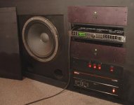
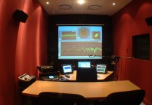
The speakers are soffit mounted on a wood wall at both sides of the video screen, slightly angled towards the mix position. The room is a mid sized audio post environment, used to mix TV shows.
The measurement mic position is at 4 meters from the front wood wall. This position does not give the best readings, mainly because of the unavoidable reflections from the desk and computer monitors, but THAT is the place where the person that makes decisions about the audio of a show is, so I had to battle to make it work.
The amplifier cluster is below the screen, right of the subwoofer.
Sorry abut the quality of the photo, and I hope you fiind it usefull.
Cheers
Ric
Da5id4Vz said:As an Old 809 user, I find this very interesting.
Can you show us a wide shot of your listening space. Your equipment rack is intriguing.
Thanks.
-Dave
The speakers are soffit mounted on a wood wall at both sides of the video screen, slightly angled towards the mix position. The room is a mid sized audio post environment, used to mix TV shows.
The measurement mic position is at 4 meters from the front wood wall. This position does not give the best readings, mainly because of the unavoidable reflections from the desk and computer monitors, but THAT is the place where the person that makes decisions about the audio of a show is, so I had to battle to make it work.
The amplifier cluster is below the screen, right of the subwoofer.
Sorry abut the quality of the photo, and I hope you fiind it usefull.
Cheers
Ric
Attachments
Vpc
This is running in an old Titanium 400 with a generic USB->Serial adaptor, but you are right, it would run without a problem from any ancient machine ( a Quadra 650 may be?) running VPC 2 or 3 plus W98. And that machines even have a pair of nice serial ports buit in!
I had to study this issue for some time, and this forum was an invaluable resource. I’ve learn a lot from well-written and documented posts of people sharing their experiences. So this time is my turn to do so.
Cheers
Ric
planet10 said:
It is nice to see that the software runs under VirtualPC... to get a serial link do you have a card or a USB->Serial adaptor (or are running a hacked version of OS X on an old beige or somesuch)
This is running in an old Titanium 400 with a generic USB->Serial adaptor, but you are right, it would run without a problem from any ancient machine ( a Quadra 650 may be?) running VPC 2 or 3 plus W98. And that machines even have a pair of nice serial ports buit in!
Well documented... good on you.
dave
I had to study this issue for some time, and this forum was an invaluable resource. I’ve learn a lot from well-written and documented posts of people sharing their experiences. So this time is my turn to do so.
Cheers
Ric
Thanks for the photo. Its a nice looking room.
It looks like you’ve got Metric Halo showing on the big screen, Genelec 1030 for the near fields and a DSP-DAW. (and of course the ever present RM-450 layback controller)
Can you tell us your impressions of the upgraded 809 vs the near field? (oops, just re-read the tread)
Reason I asked is that the millwork for the amp rack peaked my interest to check your bio. I built a number of mix to pix rooms, back when I was young, and still worked in television.
Deafening light
Ah, yes, right, “instant thermal compression”. People really liked that. Most of them deaf by now. You really had to produce high SPL to get that “light”. Not my cup of coffee.
Well, now we have Waves L1, which is very often abused….
Cheers
Ric
Da5id4Vz said:Remember the 813s had those cool non-linear ressitors in the crossover network. Engineers used to say the mix was loud enough when they made the speakers light up.
Ah, yes, right, “instant thermal compression”. People really liked that. Most of them deaf by now. You really had to produce high SPL to get that “light”. Not my cup of coffee.
Well, now we have Waves L1, which is very often abused….
Cheers
Ric
Starting point graphics
Once the amps were ready and tested, the crossover was connected to the amp. The signal path was all-digital as follows:
1-Pro Tools digital audio workstation as a player. I do not have a really “audiophile” CD player, so to get the best sound reproduction the tunes were extracted digitally direct to hard disk and played in 44.1K/16 bits thru a Pro Tools HD software and a Digidesign 96 I/O interface.
The signal is piped to the crossover thru an AES digital connection.
From Crossover outs to Amplifiers an unbalanced connection was used. Due to the short distance (20 cm length) from the crossover to the amp, a balanced connection was overkill, and would only add complexity to the Amp.
Playing pink noise thru the system, the preliminary Db vs. Frequency graph was like this (see picture). Note the awful holes at the crossover points (around 1.5K and 7.5K). You can see there are some nasty peaks at the bottom, a combination of the speakers ‘s soffit mount technique and room modes.
As you can guess, this didn’t sound any good.
Next: phase graph
Attachments
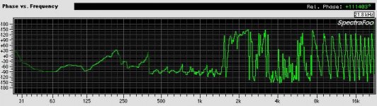
Preliminar phase response
Preliminar phase response was also not good at all. This was obtained aligning the delay channel of the meter with the woofer delay. Note that the horn and the tweeter ar off by a big margin.
next: after tweaking measurements.
Preliminar phase response was also not good at all. This was obtained aligning the delay channel of the meter with the woofer delay. Note that the horn and the tweeter ar off by a big margin.
next: after tweaking measurements.
Attachments
Adjustments
Crossover filters and points
When everything was connected and that preliminary awful response plots were acquired it was time to play with the crossover filters. At first a LR 24 db/oct filters at 2 KHz were chosen for the woofer to horn transition and the same for the Horn to tweeter at 10 K. That arrangement produced two very deep holes at the crossover points. I tried more pronounced slopes (48db) but the holes were still there. After some time trying different combinations, a 24 db/oct butterworth LP filter at 1.66 KHz was chosen for the woofer and an 18 db/oct butterworth for the matching HP filter on the horn. That combination provided a seamless transition between these drivers-see pictures. I wanted to try lowering the crossing point –It’s so easy with digital- to see if I could set it to 1.2 KHz but the horn didn’t like it very much so I returned to 1.6 KHz.
For the horn/tweeter transition an 18 db/oct LP at 7.2 KHz did it for the horn and on the tweeter side a 24 db/oct butterworth worked the best, again with minimal transitional effects. At first a 10 KHz crossover point was chosen, but the horn really begins to decay and sound nasty after 8 K, so I had to lower that point to 7.2 K. With that, the tweeter will have to work more but the difference in transparency and distortion is very noticeable.
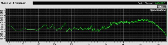
Delay:
Since the horn is firing from the back of the woofer, that is the zero delay point. The woofer had to be delayed by .22 mS and the tweeter .59 mS. once that small delays were dialed up, the phase really lmproved. Now take a look a the new phase response graphic and compare it to the original. It looks and sounds different.
Crossover filters and points
When everything was connected and that preliminary awful response plots were acquired it was time to play with the crossover filters. At first a LR 24 db/oct filters at 2 KHz were chosen for the woofer to horn transition and the same for the Horn to tweeter at 10 K. That arrangement produced two very deep holes at the crossover points. I tried more pronounced slopes (48db) but the holes were still there. After some time trying different combinations, a 24 db/oct butterworth LP filter at 1.66 KHz was chosen for the woofer and an 18 db/oct butterworth for the matching HP filter on the horn. That combination provided a seamless transition between these drivers-see pictures. I wanted to try lowering the crossing point –It’s so easy with digital- to see if I could set it to 1.2 KHz but the horn didn’t like it very much so I returned to 1.6 KHz.
For the horn/tweeter transition an 18 db/oct LP at 7.2 KHz did it for the horn and on the tweeter side a 24 db/oct butterworth worked the best, again with minimal transitional effects. At first a 10 KHz crossover point was chosen, but the horn really begins to decay and sound nasty after 8 K, so I had to lower that point to 7.2 K. With that, the tweeter will have to work more but the difference in transparency and distortion is very noticeable.
Delay:
Since the horn is firing from the back of the woofer, that is the zero delay point. The woofer had to be delayed by .22 mS and the tweeter .59 mS. once that small delays were dialed up, the phase really lmproved. Now take a look a the new phase response graphic and compare it to the original. It looks and sounds different.
Attachments
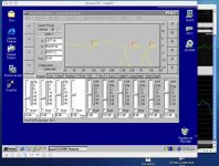
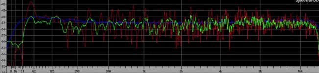
Current frequency plot
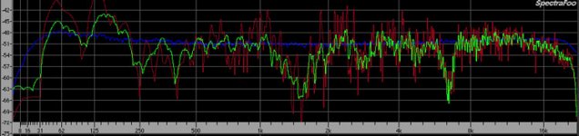
Finally I can show the Frequency graph after equalization. Blue line is pink noise, red line is instantaneous peak and green is average.
Two parametric stages on the woofer and one on the horn were used. The tweeter band does not carry anything on it. The crossover still have around 8% processing power left, may be good for another 2 or 3 parametric bands, which can make the graph look more "table like", but I feel is good enough for now. Overcompensating for one place (operator's seat) introduces unbalances on the rest of the listening space.
This is more or less the current state of the situation. I still have a few comments on adjusting the limiters and related subjective evaluation of the sound, that someone can find interesting or not. I'm open to debate.
And I think that although this is a special case of using this crossover and GC amplification, this exercise can show what can be done today with a reduced budget and some time and patience.
Cheers
Ric
Attachments
- Status
- This old topic is closed. If you want to reopen this topic, contact a moderator using the "Report Post" button.
- Home
- Loudspeakers
- Multi-Way
- Urei 809 + Behringer 2496 + Gainclone Mod.