Sorry tortello77, I missed that one.Thanks Steve, from the graphs would do you think would be the best cap/inductor combination to use on the woofer?

Bass filters:
2mH, 4.7uF, 2.2R
1.5mH, 6.8uF, 3.3R
1mH, 8.2uF, 4.7R
Would all get you to a similar place. But the big coils sound bassier. The little coils are louder in the midrange.
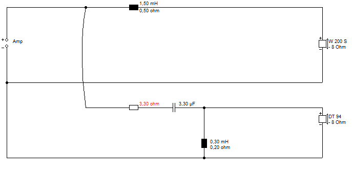
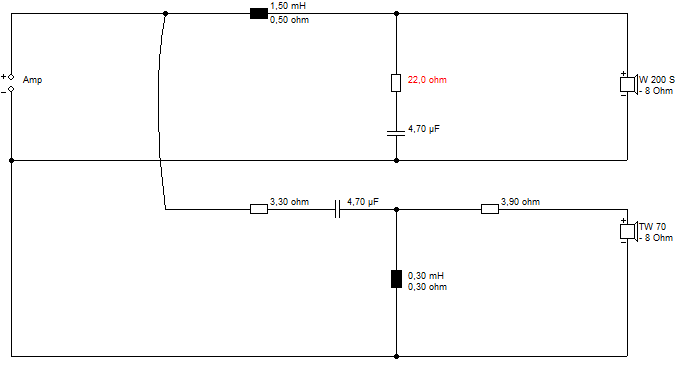
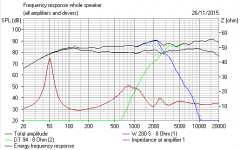
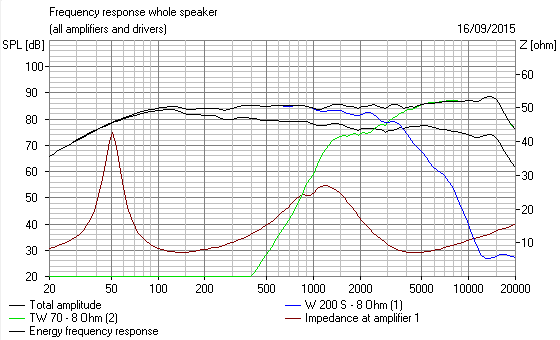
The two graphs show the shallow and the steeper response of the two types of filter I showed you earlier. Simple and more complex. An estimate. You will have to adjust tweeter level with the red resistor.
Last edited:

The impedance of an LC filter is related to root L/C. Might be a 2 Pi in there too, can't remember. The -3dB point is related to 1/ root LC.
This also tells you what resistor it is going to work with. However a speaker is best modelled electrically as an inductor Le in series with the resistance Rdc.
You compensate for that with the shunt resistance. Underdamped, it produces a peaky 3rd order electrically. Overdamped it becomes a shallow second order. Get it right, and you end up somewhere around 3rd order butterworth slopes. This is controlling the Q of the filter really.
Hence it's nice to know the Le inductance of the speaker. If it's low or around 0.6mH, you don't need the resistor. When it's high, say 2.2mH you might need 7.5R.
I've done a bit of a one-size fits all here. You bass is probably highish inductance from all accounts, sounding bassy. If you take out the 3.3R, you get an underdamped peak at 3kHz crossover as shown for the second order bass with the third order tweeter.
Attachments
0.78mH is going to be quite easy and predictable to work with. You need less shunt resistance to avoid that peakiness. But, TBH, I think 3.3R is still going to do the right things here.
I think you've just got to experiment. None of those circuits I gave you sound bad. Marco-Gea used a very low inductance PA driver here: http://www.diyaudio.com/forums/multi-way/147632-classic-monitor-designs-25.html#post4428857
But it's also rather a different tweeter and lower crossover.
I think you've just got to experiment. None of those circuits I gave you sound bad. Marco-Gea used a very low inductance PA driver here: http://www.diyaudio.com/forums/multi-way/147632-classic-monitor-designs-25.html#post4428857
But it's also rather a different tweeter and lower crossover.
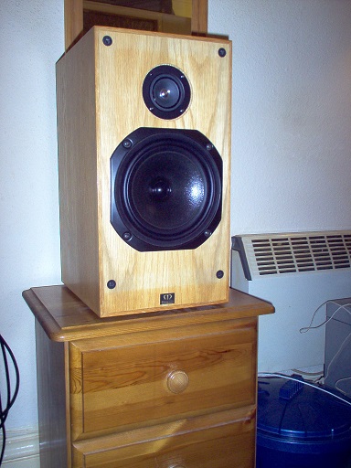
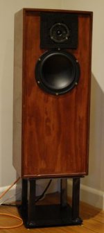
Hi guys, just wanted to thank everyone of you, and take the opportunity to post a couple of pictures of the speakers, Thanks!!
An externally hosted image should be here but it was not working when we last tested it.
An externally hosted image should be here but it was not working when we last tested it.
I'll try again
An externally hosted image should be here but it was not working when we last tested it.

- Status
- This old topic is closed. If you want to reopen this topic, contact a moderator using the "Report Post" button.
- Home
- Loudspeakers
- Multi-Way
- help with low pass filter for 2 way speakers!!