Hey all,
It's been a while since I've been on here! I need some help from someone better versed in the TL design than me.
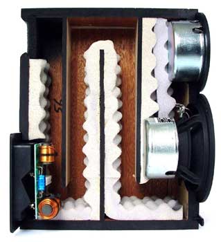
I bought a pair of PMC TB1s super cheap on eBay to add to my studio. I've been struggling with a big 50hz null, which I thought was the room, but after measuring closer to the speaker it looks like it might be the stuffing in the TL They had some black foam covering the rear ports, which was starting to crumble, and completely fell out when I pushed it.
I've experimented with an RTA mic 6cm from the center of the woofer. I took 3 measurements, one without the foam, one with the original foam (which did very little in it's current form) and one with a rolled up tea towel stuffed in the port, quite loosely but enough that it's fairly sealed.

They sound much better stuffed, although I feel like they've lost some "life". Could anyone advise me on a better way of going about this? What materials should I look at? Is this port supposed to be fairly open, in which case is this a driver issue? I noticed that my LEAK 3090 TLs only have a bit of speaker grill across the ports, although they are front firing.
Many thanks,
Blindmelon6
It's been a while since I've been on here! I need some help from someone better versed in the TL design than me.
I bought a pair of PMC TB1s super cheap on eBay to add to my studio. I've been struggling with a big 50hz null, which I thought was the room, but after measuring closer to the speaker it looks like it might be the stuffing in the TL They had some black foam covering the rear ports, which was starting to crumble, and completely fell out when I pushed it.
I've experimented with an RTA mic 6cm from the center of the woofer. I took 3 measurements, one without the foam, one with the original foam (which did very little in it's current form) and one with a rolled up tea towel stuffed in the port, quite loosely but enough that it's fairly sealed.
They sound much better stuffed, although I feel like they've lost some "life". Could anyone advise me on a better way of going about this? What materials should I look at? Is this port supposed to be fairly open, in which case is this a driver issue? I noticed that my LEAK 3090 TLs only have a bit of speaker grill across the ports, although they are front firing.
Many thanks,
Blindmelon6
Have a look at the PMC ATL: What's this ATL all about then? - Carlton Audio Visual - Hi Fi & Audio Visual Store, Melbourne Australia. There's probably much more foam in your speaker than what you see in the port.
The null at 50 Hz is not really an issue, the other side of the coin is the port, which reaches its maximum output at the same frequency. Measure it in the same way as the driver.
The null at 50 Hz is not really an issue, the other side of the coin is the port, which reaches its maximum output at the same frequency. Measure it in the same way as the driver.
Have a look at the PMC ATL: What's this ATL all about then? - Carlton Audio Visual - Hi Fi & Audio Visual Store, Melbourne Australia. There's probably much more foam in your speaker than what you see in the port.
The null at 50 Hz is not really an issue, the other side of the coin is the port, which reaches its maximum output at the same frequency. Measure it in the same way as the driver.
In this PMC video that they tried to explain what ATL is, they mentioned IMF and TDL who were the pioneers of the transmission line and aperiodic cabinet. The PMC person mentioned that the sound wave coming out of the port is "exactly in phase" with the front woofer wave. That means the equivalent wavelength of the internal acoustic tunnel is at the half wavelength of the woofer resonance. That's how the original Bradley transmission line speaker was designed. IMF and TDL substituted the long fiber wool with open cell foam and achieve the same phase inverting effect. If PMC achieve what they claim, it should not have the 50Hz null.
The foam at the port indicated that the PMC TB1 is a hybrid TL/aperiodic design. You may need to replace the foam inside the cabinet too. You can find open cell, medium density foam at most fibre and sewing supply store. It is best to contact PMC about the foam replacement. PMC said that their foam was specially manufactured by themself.
The output from the port of a quarter wavelength line is not in phase with the woofer front wave, thus, acting like a bass reflex box instead.
Last edited:
Despite what keilau claims Bailey's line, IMFs & TDLs are all 1/4 wave resonators. A 1/2 wave line has to be either open or closed at both ends.
According to PMC it is a 71 Hz line.
How are you measuring? Unless you are outside and something over 20 ft up, face up buried in the ground, in an anechoic chamber, or doing a measure with the micon the woofer you cannot get the room out of that measure.
If you are doing the last there will be a null in the woofer at the primary output of the terminus. You'd have to measure that separately and add the 2 together (taking care of all the adjustments you need to make to add them together).
Foam does not make for great stuffing.
dave
Despite what keilau claims Bailey's line, IMFs & TDLs are all 1/4 wave resonators. A 1/2 wave line has to be either open or closed at both ends.
According to PMC it is a 71 Hz line.
How are you measuring? Unless you are outside and something over 20 ft up, face up buried in the ground, in an anechoic chamber, or doing a measure with the micon the woofer you cannot get the room out of that measure.
If you are doing the last there will be a null in the woofer at the primary output of the terminus. You'd have to measure that separately and add the 2 together (taking care of all the adjustments you need to make to add them together).
Foam does not make for great stuffing.
dave
I'm measuring on well isolated stands in a fairly well treated room. Bottom end is a little lumpy on my other speakers, but the main dip is more in the 40hz region.
I'd be inclined to agree with you were it not for the fact that the frequency response is also improved at the listening position, and shows no negative effects in a waterfall plot. I'll post some more measurements this evening.
In the mean time in thinking it might be with trying to contact PMC (why oh why didn't I just shell out for a new pair
 )
)Despite what keilau claims Bailey's line, IMFs & TDLs are all 1/4 wave resonators. A 1/2 wave line has to be either open or closed at both ends.
According to PMC it is a 71 Hz line.
How are you measuring? Unless you are outside and something over 20 ft up, face up buried in the ground, in an anechoic chamber, or doing a measure with the micon the woofer you cannot get the room out of that measure.
If you are doing the last there will be a null in the woofer at the primary output of the terminus. You'd have to measure that separately and add the 2 together (taking care of all the adjustments you need to make to add them together).
Foam does not make for great stuffing.
dave
Dave, can you provide a link to the PMC "71Hz line" claim? It is not fair for you to make that statement without substantiating it.
You can deny all the wonderful test and analysis that Bailey and Bradbury did. But their mathematics convinced me that a transmission line has to be 1/2 wave line to work the way they claimed and measured. You can deny science, but it does not make science not true. Every college physics student knows that sound pressure adds when in phase and subtracts when out of phase. 90 degrees out of phase (1/4 wave) is somewhere in between.
If you want to claim that the IMF and TDL speakers do not work the way the manufacturers claimed and open cell foam is a poor stuffing material, you need to provide your own measurement with details on the type of foam that you used and how you measure.
IMF electronics
I heard Bud Fried demonstrated his product many, many years ago and was convinced that his lines work the same way as Bailey's. Bud Fried can longer argue with you in person.
I do know that polyester or glass fiber do not work well in transmission line as demonstrated by Bailey and Bradbury. Polyester or glass fiber do not slow down sound wave at low frequency and attenuate sound wave at high frequency the same way as long fiber wool.
Last edited:
Dear Keilau,
The impedance curves of the IMF and TDL speakers, with their double peaks clearly show the system is resonant in its nature and therefore does not work as their designer seem to claim, their claim being it is basically a non-resonant loudspeaker system.
Wasn't that the title of Bailey's original WW article?
Regards,
Eelco
Would you agree that there is something very wrong with the response of these speakers, or am I expecting too much from them?
I plan on trying a couple of things. Firstly a measurement in a different room, then a measurement in as near to anechoic conditions as I can manage (I have 12 x 200mm Rockwool panels to play with.)
I plan on trying a couple of things. Firstly a measurement in a different room, then a measurement in as near to anechoic conditions as I can manage (I have 12 x 200mm Rockwool panels to play with.)
Is the straight, non dipped line the "towel-in-the-exit"? I have trouble decyphering your graphs, coz the colors look very alike
Yeah, the straight one is the towel, the dip is with the old foam.
I'll post the in room response as well, which was also greatly improved.
This paper explains in detail how a transmission line speaker works including plots of what the driver and port should be doing. As mentioned earlier, the null at the driver is probably not a problem because the output should be coming from the port at this frequency.Would you agree that there is something very wrong with the response of these speakers, or am I expecting too much from them?
As Dave said, a line that's closed on one end and open on the other will have its 1/4-wavelength frequency as the primary resonance. It has no choice and there's nothing you can do to change that. Also, polyester fiber works exactly the same way as long-fiber wool; neither literally slows down the speed of sound as Bailey thought/claimed and you simply need a stuffing density appropriate for the material used. A TL is inherently a 4th-order system and there will always be a dip in the driver's output at approximately the same frequency as the peak in the terminus' output.
Paul
Paul
Dave, can you provide a link to the PMC "71Hz line" claim? It is not fair for you to make that statement without substantiating it.
You can deny all the wonderful test and analysis that Bailey and Bradbury did. But their mathematics convinced me that a transmission line has to be 1/2 wave line to work the way they claimed and measured. You can deny science, but it does not make science not true. Every college physics student knows that sound pressure adds when in phase and subtracts when out of phase. 90 degrees out of phase (1/4 wave) is somewhere in between.
If you want to claim that the IMF and TDL speakers do not work the way the manufacturers claimed and open cell foam is a poor stuffing material, you need to provide your own measurement with details on the type of foam that you used and how you measure.
IMF electronics
I heard Bud Fried demonstrated his product many, many years ago and was convinced that his lines work the same way as Bailey's. Bud Fried can longer argue with you in person.
I do know that polyester or glass fiber do not work well in transmission line as demonstrated by Bailey and Bradbury. Polyester or glass fiber do not slow down sound wave at low frequency and attenuate sound wave at high frequency the same way as long fiber wool.
can you provide a link to the PMC "71Hz line" claim?
Right in the specs. 4' line.
You can deny all the wonderful test and analysis that Bailey and Bradbury did.
You, me, and others have all been thru that before, i'm not going thru your crap again.
dave
This paper explains in detail how a transmission line speaker works including plots of what the driver and port should be doing. As mentioned earlier, the null at the driver is probably not a problem because the output should be coming from the port at this frequency.
The Martin King design is a variant of the bass reflex as shown by its twin peaks impedance curve. In a transmission line, the output from the termus is in phase with the woofer front wave as shown in these classic papers from the two English academia:
http://user.faktiskt.se/lennartj/Audio/Bailey-1972-Transmission-Line-Loudspeaker-Enclosure.pdf
AES E-Library The Use of Fibrous Materials in Loudspeaker Enclosures
I am not a researcher in audio engineering like Arthur Bailey or Lindsey Bradbury. I do know a thing or two about physics and mathematics to appreciate the wonderful works these 2 professors did to establish the basis of transmission line speakers.
Well, I rest my case. The dip is typical for reflex type enclosures. It seems the system is -without heavy damping in the line itself- acting as a pseudo-reflex type bass loading.
You have a good point. If the foam deteriorated over time and became ineffective, the PMC cabinet may have become a bass reflex box until the foam is replaced.
The measurement of the impedance is a very good indication of this. A single peak near the woofer free resonant frequency Fs indicates a successful transmission line design or an aperiodic one. A twin peaks impedance indicates a bass reflex cabinet.
Can you provide a link to the web page that shows the impedance curves of your statement below?
Boden said:The impedance curves of the IMF and TDL speakers, with their double peaks clearly show the system is resonant in its nature and therefore does not work as their designer seem to claim, their claim being it is basically a non-resonant loudspeaker system.
Some people claimed that "polyester fiber works exactly the same way as long-fiber wool", but never showed any evidence of it. They just chose to ignore the analysis and how well the test agrees in the Bradbury paper. Bradbury showed how rigorous scientific/engineering research should be done.
It is true if you replace the long fiber wool or open cell foam in a Bailey/IMF/TDL transmission line with polyester fiber, you can turn transmission line speaker into a resonant bass reflex box too. Both the SPL and impedance will be completely different using different stuffing. It is the simple basic physics that Bradbury demonstrated.
Last edited:
ANY box that has an open end and a closed end is inherently a 4th-order system, whether you call it a BR, vented box or TL based on the box's dimensions. All of them will have twin impedance peaks but if you use enough stuffing by density and/or length to completely squash the impedance peak at the lower frequency, then all of the output will come from the driver and absolutely zero from the port of a BR/vented box or terminus from a TL. In the latter case you've managed to throw away all of the bass contribution from the terminus and converted the TL to essentially a complex, sealed box in its performance, so why bother?
Based on my BSEE education I, too, know a thing or two about physics and mathematics, and you're talking through your hat, so I'm going to do like Planet 10 and ignore you here on.
Paul
Based on my BSEE education I, too, know a thing or two about physics and mathematics, and you're talking through your hat, so I'm going to do like Planet 10 and ignore you here on.
Paul
The Martin King design is a variant of the bass reflex as shown by its twin peaks impedance curve. In a transmission line, the output from the termus is in phase with the woofer front wave as shown in these classic papers from the two English academia:
http://user.faktiskt.se/lennartj/Audio/Bailey-1972-Transmission-Line-Loudspeaker-Enclosure.pdf
AES E-Library The Use of Fibrous Materials in Loudspeaker Enclosures
I am not a researcher in audio engineering like Arthur Bailey or Lindsey Bradbury. I do know a thing or two about physics and mathematics to appreciate the wonderful works these 2 professors did to establish the basis of transmission line speakers.
You have a good point. If the foam deteriorated over time and became ineffective, the PMC cabinet may have become a bass reflex box until the foam is replaced.
The measurement of the impedance is a very good indication of this. A single peak near the woofer free resonant frequency Fs indicates a successful transmission line design or an aperiodic one. A twin peaks impedance indicates a bass reflex cabinet.
Can you provide a link to the web page that shows the impedance curves of your statement below?
Some people claimed that "polyester fiber works exactly the same way as long-fiber wool", but never showed any evidence of it. They just chose to ignore the analysis and how well the test agrees in the Bradbury paper. Bradbury showed how rigorous scientific/engineering research should be done.
It is true if you replace the long fiber wool or open cell foam in a Bailey/IMF/TDL transmission line with polyester fiber, you can turn transmission line speaker into a resonant bass reflex box too. Both the SPL and impedance will be completely different using different stuffing. It is the simple basic physics that Bradbury demonstrated.
In that case you will recognise that a bass reflex port is a Helmholtz resonator where the slug of air in the port moves in an incompressible manner with the trapped air in the cabinet acting as a spring. The compressible resonances in a typical bass reflex port occur at a few hundred Hz and are not wanted.I do know a thing or two about physics and mathematics to appreciate the wonderful works these 2 professors did to establish the basis of transmission line speakers.
A transmission line on the other hand works with the compressible resonances not an incompressible one. Ideally the lowest resonance which is wanted should travel the length of the pipe with little damping whereas the higher resonances which are not wanted should ideally be damped away by the stuffing in the pipe.
Is this simple explanation wrong? If so, in what way.
Is this simple explanation wrong? If so, in what way.
The key of a Bailey/IMF/TDL transmission line is the non-linear (frequency dependent) response of the stuffed line. Lindsey Bradbury used linear algebra (complex number theory) to create a simple model for it and showed that the theory and test data had excellent agreement. (You have it right partially when you said that LF and HF responses are different in a TL.)
A linear filter based theory works well for the closed box or bass reflex box. It cannot model the frequency dependent response of a long fiber wool filled line which is non-resonant. BTW, the air velocity in a TL box is too slow to have compressible effect. (See the explanation of how TL work by Bradbury and how well his calculation and test data agree.)
The transmission line theory is solely the credit of Bailey and Bradbury. Read their publications that I posted earlier.
If anyone wants to discredit the theory by Bailey and Bradbury, he should show how the acoutic wave travel in a long fiber filled line different from what Bradbury described.
The issue was that you incorrectly stated that the article cited containing detailed plots and information for the OP to check that his speaker was behaving correctly was for a bass reflex design rather than a speaker like his. Hopefully he now has enough information to confidently disregard your comment.If anyone wants to discredit the theory by Bailey and Bradbury, he should show how the acoutic wave travel in a long fiber filled line different from what Bradbury described.
Quite why you are banging on about what you are banging about I don't know but it seems irrelevant to the current thread and I guess is coming from a dispute you had with someone else in the past. If you want to resurrect it can I suggest you put aside personalities and debate the physics. For example, why the line length should be quarter or a half or whatever, whether the stuffing alters the speed of sound, whether the air column remains incompressible and moves as a slug or whether it compresses with sound waves travelling up and down, etc... Lots of people can join in this sort of discussion without rancour.
- Status
- This old topic is closed. If you want to reopen this topic, contact a moderator using the "Report Post" button.
- Home
- Loudspeakers
- Multi-Way
- PMC TL Stuffing