I built an econowave style speaker for my friend's garage. I used a community 15" pro driver and the Dayton D250 for HF crossed at 1100hz and it sounds Ok. I was looking at the next iteration though and that is to replace the top with a unity style horn - HF and MF.
I been reading through the various threads on unity/snergy horns and here is what I think I have learned so far:
o the MF tap has to be within 1/2 wavelength from the center of HF;
o the circumference of the cross sectional area of the tap is equal to one wavelength;
o The tap holes should be about 1/2" (round or oval) in the corners of the horn and back side should be shaped like a frustrum (wider to small). (let me know if any assumptions are incorrect).
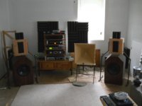
I cobbled together a 60 degree X 60 degree out of fiber board as a trial. I put two CHBW-70s on opposing sides and wired it into my 3 way active system. It was very impressive. Tom Danley is a genius and I want to acknowledge that.
Before I proceed with the real build, I had several questions.
Are two drivers sufficient or do I need four?
What is the highest realistic MF frequency I can reach? I see 1200hz mentioned many times
What is the cancellation notch or how do I derive it?
I wanted to keep it to a manageable size. Can the depth be limited to any value after one full wavelength of the MF?
Example:
1300hz as MF upper frequency
10.3" in circumference for tap
5" or less to center of HF (1/2 wavelength)
10.3" or more for depth
Please don't ask me to learn hornresp. It seems way to complicated.

I been reading through the various threads on unity/snergy horns and here is what I think I have learned so far:
o the MF tap has to be within 1/2 wavelength from the center of HF;
o the circumference of the cross sectional area of the tap is equal to one wavelength;
o The tap holes should be about 1/2" (round or oval) in the corners of the horn and back side should be shaped like a frustrum (wider to small). (let me know if any assumptions are incorrect).
I cobbled together a 60 degree X 60 degree out of fiber board as a trial. I put two CHBW-70s on opposing sides and wired it into my 3 way active system. It was very impressive. Tom Danley is a genius and I want to acknowledge that.
Before I proceed with the real build, I had several questions.
Are two drivers sufficient or do I need four?
What is the highest realistic MF frequency I can reach? I see 1200hz mentioned many times
What is the cancellation notch or how do I derive it?
I wanted to keep it to a manageable size. Can the depth be limited to any value after one full wavelength of the MF?
Example:
1300hz as MF upper frequency
10.3" in circumference for tap
5" or less to center of HF (1/2 wavelength)
10.3" or more for depth
Please don't ask me to learn hornresp. It seems way to complicated.

Rb,Before I proceed with the real build, I had several questions.
1) Are two drivers sufficient or do I need four?
2) What is the highest realistic MF frequency I can reach? I see 1200hz mentioned many times
3) What is the cancellation notch or how do I derive it?
4) I wanted to keep it to a manageable size. Can the depth be limited to any value after one full wavelength of the MF?
Example:
1300hz as MF upper frequency
10.3" in circumference for tap
5" or less to center of HF (1/2 wavelength)
10.3" or more for depth
5)Please don't ask me to learn hornresp. It seems way to complicated.
1) Depends on the SPL level desired, 4 drivers will have 6 dB more SPL potential than two.
2) Appears your horn is about -3 dB at 1500 Hz, so 1200 Hz obviously is not a hard limit. The top end is determined by interactions between driver size and position and port size and volume behind the port, all of which determine an acoustical low pass filter.
3) I'll quote Tom Danley from yesterday on Audio Asylum: "When you have a closed end duct or horn and the source is between the open end and closed end, there is a reflection from the closed end back to the source. When that reflection traverses 1/2 wavelength or multiples of that, there are cancellation notches in the response as the sound arrives delayed 180 degrees (or multiples). One sees the same thing in the mid and low frequency portions of the Synergy horns and the first notch must be above the highest frequency your using that portion to."
4) Limiting depth will also limit horn mouth size, which will reduce pattern control to a higher frequency.
Your horn presently is only a single section, not using the secondary portion of the horn results in some mid-range "waistbanding", a narrowing of dispersion which then widens back out at lower frequencies.
5) If you prefer not to learn Hornresp or go through a long trial and error period of build iterations, you may be better off simply copying a design that does what you want it to do.
Art
Thanks Art for the response. I do not want to engage you endlessly because I know that much of this you have answered many times over but I had a few follow up questions on your responses.
1. On the depth response, I thought that when a full wavelength was reached, the horn walls were no longer fully engaged.
2. On the 'waistbanding comment, I was hoping for like 400-1200 for MF. So when you say lower frequencies, you are referencing?
Thanks again for your patience.
1. On the depth response, I thought that when a full wavelength was reached, the horn walls were no longer fully engaged.
2. On the 'waistbanding comment, I was hoping for like 400-1200 for MF. So when you say lower frequencies, you are referencing?
Thanks again for your patience.
Hi rb,
The midrange ports have to be within 1 QUARTER wavelength, not half! The distance from the port to the driver diaphragm and then back again to the port is what has to be under a half wavelength.
Hornresponse isn't really very hard to learn at all. Much less work than figuring out cuts for a waveguide.
Have you seen/used my Synergy waveguide spreadsheet? It will work out dimensions for you.
1) A full wavelength of 400 Hz is 2.825 feet. I don't understand what you mean by a "fully engaged horn wall".1. On the depth response, I thought that when a full wavelength was reached, the horn walls were no longer fully engaged.
2. On the 'waistbanding comment, I was hoping for like 400-1200 for MF. So when you say lower frequencies, you are referencing?
2) "Waistbanding" due to using a single conical expansion could occur in the 400 to 1600 Hz Hz range (for typical horn sizes), the frequency would vary with horn angles and size.
I completely agree.Hornresponse isn't really very hard to learn at all. Much less work than figuring out cuts for a waveguide.
Have you seen/used my Synergy waveguide spreadsheet? It will work out dimensions for you.
And even using your spread sheet (a big help) I managed to mess up several cuts when building the SynTripP cabinets and secondary horns, probably 15 square feet of scrap pieces to the dump...
Weltersys, I have read many of these threads and it is hard to glean exactly what info that I need but it was my understanding that the bottom frequency set for the MF is set by the flare rate (and I know that you know that). When I was talking about horn wall engagement, I meant the high end of the MF which seems to be more than likely around 1100-1200. I was theorizing that I only needed an effective depth of 9-10" then. I should have been clearer.
I am planning to create another prototype (I actually have one gluing up) and add the drivers and do some measurements. I can add the secondary flare and do some measurements, etc.
I am not seeking perfection. It is for a garage and when we listen, we are usually imbibing ;-).
I also forgot to mention, I got a Behringer CX3400 x-over and equalizer which should allow me to forgo trying and 'cipher' a passive 3 way. I can not imagine trying this passively.
The midrange ports have to be within 1 QUARTER wavelength, not half! The distance from the port to the driver diaphragm and then back again to the port is what has to be under a half wavelength.
Just re-read what I had posted. By "driver" above, I meant the tweeter driver (down at the throat of the horn). Energy that comes out the midrange holes, goes toward the tweeter and bounces back to the midrange holes will cause a big cancellation notch if the total distance traveled over that is 1/2 wavelength. I.e., midrange hole needs to be within 1/4 wavelength of the tweeter's diaphragm.
I'm back.
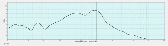
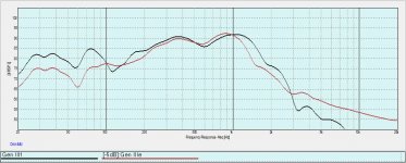
I made a smaller prototype and have not added the additional flare to it (yet). I wanted to start taking some measurements awhile. I can not get anything more than an upper end of than about 1.1k then it drops like a rock. I took measurements when the drivers were mounted 2" from the center of the tweeter and then 1-1/2". Those measurements are nearly identical. That surprised me since it was my understanding that the upper limit of the MF has to do with closeness to the center of the HF. I searched for other threads of folks who have been down this road and the only one (that I can find) that has significant upper limit on the MF is BWASLO. His chart is just shy of 2k. All the other MF ranges look very much like mine except for mtg90 who used 1/2" stand offs on his MF and that drastically cuts the high end of the MF. One of my tests was to add 1/2" stand offs and the same thing happened to my upper range. It dropped dramatically. Message to anyone that wants to make this type of speaker - do not use stand offs on your MF drivers. BWASLO has like a 50x90 horn and I believe that he used 3" drivers for his MF. Anyone else have success in extending the MF in a 60x60? BWASLO what is your secret??
I have include MF frequency charts of 2" to center and 1-1/2" to center....very much alike....
Attachments
The big 'secret' is your apparent lack of understanding band-pass alignments, which this picture is hiding two of them in plain sight ") , though of course the driver's specs come into play, so you can't just mimic them unless you're using DSL's drivers and you still have to adhere to the 1/4 WL 'rule' to get 'close enough' summation, which in turn dictates how large a driver can be used:
, though of course the driver's specs come into play, so you can't just mimic them unless you're using DSL's drivers and you still have to adhere to the 1/4 WL 'rule' to get 'close enough' summation, which in turn dictates how large a driver can be used:

When designing TL/horn alignments, understanding resonant pipe acoustics doesn't hurt either: Resonances of open air columns
GM
, though of course the driver's specs come into play, so you can't just mimic them unless you're using DSL's drivers and you still have to adhere to the 1/4 WL 'rule' to get 'close enough' summation, which in turn dictates how large a driver can be used:
When designing TL/horn alignments, understanding resonant pipe acoustics doesn't hurt either: Resonances of open air columns
GM
Thanks. That seems to address the bottom end of the MF. I was asking about the top end of the MF. Here is what I had captured from a previous thread:
These two points need to be met: the cross sectional area of the MF taps need to equal or less than 1 wavelength and the distance from the acoustical center to MF tap must be 1/4 wavelength (or less).
2000 hz is 6.75 inches = 1 wavelength for circumference and 1/4 would be 1.7" from the center. Where am I wrong?
You are not understanding what has been mentioned already:Where am I wrong?
The top end is determined by interactions between driver size and position and port size and volume behind the port, all of which determine an acoustical low pass filter.
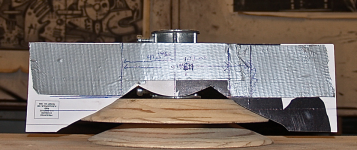
You already know that adding a spacer increases the band pass chamber volume, reducing the corner frequency, to increase the high frequency corner frequency, the air volume in front of the the cone must be minimized, while still allowing for full driver excursion without hitting the plug.
An example below, the cone filler was sanded to fit the cone contour.
The plywood circle had a bolt through it chucked into a drill press, then a belt sander was used while the disc spun to get the contour exact. A lot of work, but filling the cone area increased the top end before the acoustical band pass quite a bit.
Attachments
Last edited:
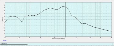
Thanks Weltersys. The light bulb sometimes comes on slowly. I kinda answered my question earlier as you did. I quick ran out to the shop and removed 3/8" of material and reattached the drivers. Guess what? I got more high end on the MF...... interesting.
Attaching a chart of the last 2 iterations.
Attaching a chart of the last 2 iterations.
Attachments
Weltersys,
If I could fashion a concave shape out of foam that sits inside of the surround (does not interfere) and decreases the volume even more, I can get more high end to the MF? It might be worth an experiment.
I think that is what you were explaining with your last paragraph in your post.
If I could fashion a concave shape out of foam that sits inside of the surround (does not interfere) and decreases the volume even more, I can get more high end to the MF? It might be worth an experiment.
I think that is what you were explaining with your last paragraph in your post.
Dont forget that the length that is already INSIDE the tweeter driver (from its diaphragm to its mounting plate) also forms part of that distance. Look inside your driver, there might be nearly an inch already in there (tweeter driver choice matters a lot). You have to include that in the distance that has to stay under 1/4 wave! If you want to get to 2kHz then, that would leave you only about a half inch in the part of the horn you build.
While you're designing, also keep the mid openings within 1/4 wave of each other if the coverage angle will be wide, or pattern problems might happen. Don't sacrifice that just to force the openings into corners.
Also don't get hung up on the cross sectional area bit unless max sensitivity is more important that smoothness. In general, the design rules I ended up with for high xover point are:
1) mid openings as close as possible to the throat. No matter what.
2) short path within the tweeter itself.
3) related: wide as possible exit angle in the tweeter.
Which is how I ended up with the CDX1-1445 and 2" midrange...
Last edited:
- Status
- This old topic is closed. If you want to reopen this topic, contact a moderator using the "Report Post" button.
- Home
- Loudspeakers
- Multi-Way
- Questions on Synergy/Unity Horn