AR Series components
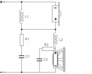
To demystify the AR series xo, here's what the components do.
L1 sets the crossover roll off for the tweeter, lower the value to increase xo point and visa versa (very low DCR air core required).
R1 sets the tweeter level and must be above 3R so the speaker impedance does not drop. Tweeter SPL choice is important and must be higher than the mid woofer by a couple of dB to achieve this. Impedance of the tweeter can come into play (such as the XT25). Use a 10W ceramic or Mox resistor or equiv.
C1 sets the crossover roll off for the woofer in conjunction with L2 as well as the slope of the tweeter roll off. It effects both the woofer and the tweeter so a change effects both. Higher value increases slopes. Use a good quality MKP here.
L2 sets the crossover roll off for the woofer as well as the BSC. Larger value will drop the xo point, increase BSC possibilities and visa versa. It can be placed on the -ve line between C1 and C2. Use a good quality air core but DCR has to be noted in the modelling as does effect the result.
C2 and R2 forms the CR (zobel) and helps with final tweaking of the phase and roll off. Rarely is it a textbook value.
C2 value can be altered to change the woofer roll off slope etc (larger will make it steeper). Use a MKP.
R2 can be tweaked to help with phase at the crossover point so you end up with a deep reverse null of 30dB+. Use a 10W ceramic or MOX.
Optional components:
A cap can be included in series after L1 and before the tweeter but usually not required and can cause phase issues which means a complete redesign.
The tweeter can have a damping resistor across the tweeter to lower the impedance peak and 15R-22R is a good place to start. However, R1 would have to be decreased in value as you get added attenuation of the tweeter.
CR can be placed across the tweeter to help shaping of tweeter response and a good example of this is the 810921 tweeter.
LCR networks can be added if desired but every component in series xo effects everything else. Generally not required if driver choice is good.
Find Jeff Bagby's SCD, create some frd and zma files and have a play.
Attachments
C1 sets the crossover roll off for the woofer in conjunction with L2 as well as the slope of the tweeter roll off. It effects both the woofer and the tweeter so a change effects both. Higher value increases slopes. Use a good quality MKP here.
C2 value can be altered to change the woofer roll off slope etc (larger will make it steeper). Use a MKP.
Optional components:
A cap can be included in series after L1 and before the tweeter but usually not required and can cause phase issues which means a complete redesign.
Find Jeff Bagby's SCD, create some frd and zma files and have a play.
The electrical slope from the SXO cannot increase just by increasing the value of a capacitor, it will still transition to the inherent slope further down the rolloff. It can however change the shape of the knee at the xover which will add or remove damping to the knee depending on value. This is the same with parallel networks as well.
As to the AR-SXO design as a whole, yes- the added cap on the tweeter would alter how close the summation gets using this circuit and voicing by ear. It is likely that on a flat baffle you can't have the second order SXO and have it work well anyway. This is due to the acoustic offsets, and a typical 12/18 arrangement of acoustic slope is what makes them align better in general. The 1st on tweeter and 12dB on the woofer is why the alignment works as it is most of the time.
PCD now has SXO modelling in the same spreadsheet, so you only have to DL PCD for both. Be sure to get Response Modeler so you adapt your files to your boxes before using it though.
Later,
Wolf
Clearly I admit that I am a hack, with no software or measuring equipment used in my designs but as i have been building by ear for 7 years and analysing Tony Gee, Troels G etc. and great info From great people in this forum I am happy with my results. I am yet to burn a voice coil on any drivers with my guestimate designs nor send any amps into meltdown. So with that i will continue to build em like this.
of course what Rabbitz says is correct about selecting the correct drivers and on occasions i have ignored that but hey its my money, my time and my fun.
cheers friends.
just remember its just a bit of fun.
of course what Rabbitz says is correct about selecting the correct drivers and on occasions i have ignored that but hey its my money, my time and my fun.
cheers friends.
just remember its just a bit of fun.
I do hope this series discussion manages to stay on-topic and actually INFORM, because most of them don't!
Since Jonathan (chefsinc) started his SB 8" plus 1" project, I've spent a lot of time at Tony Gee's marvellous Humble Homemade Hifi website. The Extremon (found in components/downloads) is a very nice flat baffle 6" Paper plus 1" (SEAS 22TAF/G) design using a series network.
It's quite easy to get as good as you like using Parallel or Series networks, and you can throw some nice notches in with both. The interesting thing happens when you TIME ALIGN it by setting the tweeter back and flipping the polarity.
Suddenly you find all the notches are disastrous to phase, and you must dump them!
So you have to live with higher Fs resonance and 5kHz cone breakup. But the good news is 1) You get a simple fast circuit, and 2) All the resonances are PHASE ALIGNED, so may be less offensive. Series circuits become very appealing when time-aligned, but you CAN do similar stuff with parallel. Like metal cones, they are a strict discipline, but you will learn lots.
It's a matter of technique to adjust the circuits when dumping the notches, and I won't dwell on it, except to say that losing the 15uF DC-blocking capacitor was a very double-edged sword. But these are low-order circuits that make demands on drivers, and series filters tend to let a lot of low frequencies into the tweeter. So some drivers will work better than others, and SMOOTH is good. For instance, this polycone SEAS U18RNX/P looks fun.
After such an epic (IMO) post, I hope for some interesting replies...but I'm not getting my hopes up.
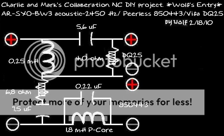
actually S7 I did dump the 15uf/or22uf in series with the tweeter in my schematic and now run it with just a 12uf after the .390mh inductor. no resistor either end, just the Lpad to dampen the tweeter output. so far 3 days and no distortion or burnout. I still think I could do a bit more to dampen the 3.5khz woofer breakup, but is only noticeable on CD's such as Adele's 21 with her high frequency voice.
Wolf, S7, Rabbits any suggestions? I tried to roll off the woofer with a bigger cap parallel to the zobel but it sounded a bit compressed. Go for a bigger L2 inductor? or just leave it as it is not that noticeable as I said only on certain CD's.
cheers guys
Jonathan
I'm not familiar with your speaker but generally I tend to reduce woofer peaks at higher frequencies with a larger L2 and a larger zobel cap for additional shaping. If I'm understanding this correctly, the larger cap parallel to the zobel will not alter the slope but move the woofer xo point down so the effect on the peak would be minimal.
I'm not familiar with your speaker but generally I tend to reduce woofer peaks at higher frequencies with a larger L2 and a larger zobel cap for additional shaping. If I'm understanding this correctly, the larger cap parallel to the zobel will not alter the slope but move the woofer xo point down so the effect on the peak would be minimal.
actually S7 I did dump the 15uf/or22uf in series with the tweeter in my schematic and now run it with just a 12uf after the .390mh inductor. no resistor either end, just the Lpad to dampen the tweeter output. so far 3 days and no distortion or burnout. I still think I could do a bit more to dampen the 3.5khz woofer breakup, but is only noticeable on CD's such as Adele's 21 with her high frequency voice.
Wolf, S7, Rabbits any suggestions? I tried to roll off the woofer with a bigger cap parallel to the zobel but it sounded a bit compressed. Go for a bigger L2 inductor? or just leave it as it is not that noticeable as I said only on certain CD's.
cheers guys
You should place a 0.1-0.22uF cap across the L2, and then a 1.5uF cap across the woofer, and you may no longer require the zobel.
It'll look like this (1.5uF cap not pictured):
Give that a shot,
Wolf
@chefsinc. I can't quite get a handle on the filter for your SB Acoustics 8" woofer yet, but I just have a feeling that a Zobel around 7.5R and 10uF might be as good as it gets after the baffelstep. That's what you do with mildly over lively woofers in general. It's not tidy or rolled-off enough to just run, almost unfiltered, on a mere coil like the famous polycone Vifa P13.
wolfie's tank is a nice idea, and quite Paul Carmody "Overnight Sensations", but sends the phase at 7.5kHz to hell in my opinion. I still don't think notches work with series circuits. What's wrong with a Zobel here?
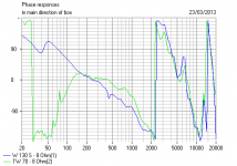
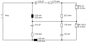
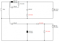
Remember samadhi's lovely Stellan speaker above? Uses a Visaton W130S 5" Woofer and a Visaton TW70 Cone Tweeter. I like the TW70, it just FITS with paper woofers very nicely. Quite how nicely, you are about to see!
I knocked up this 2nd order series crossover with the indispensable attenuator on the tweeter:
Here's the bit that made me fall off my chair in amazement.
THAT, my friends, is PERFECT phase alignment. I just can't do anything as good with a parallel circuit. It just doesn't get better than that!
wolfie's tank is a nice idea, and quite Paul Carmody "Overnight Sensations", but sends the phase at 7.5kHz to hell in my opinion. I still don't think notches work with series circuits. What's wrong with a Zobel here?
An externally hosted image should be here but it was not working when we last tested it.
Remember samadhi's lovely Stellan speaker above? Uses a Visaton W130S 5" Woofer and a Visaton TW70 Cone Tweeter. I like the TW70, it just FITS with paper woofers very nicely. Quite how nicely, you are about to see!
I knocked up this 2nd order series crossover with the indispensable attenuator on the tweeter:
An externally hosted image should be here but it was not working when we last tested it.
Here's the bit that made me fall off my chair in amazement.
An externally hosted image should be here but it was not working when we last tested it.
THAT, my friends, is PERFECT phase alignment. I just can't do anything as good with a parallel circuit. It just doesn't get better than that!
Attachments
The phase goes bouncy at 8k in my sim.
You're already far off the xover point, so it doesn't matter as much. This is w/o the 1.uF to limit the top-end woofer ripple.
Depends on your compromise.
And to say it's Paul Carmody-esque is funny- I've been doing this a lot longer than he has.
You can notch an SXO.
Wolf
You're already far off the xover point, so it doesn't matter as much. This is w/o the 1.uF to limit the top-end woofer ripple.
Depends on your compromise.
And to say it's Paul Carmody-esque is funny- I've been doing this a lot longer than he has.
You can notch an SXO.
Wolf
This post is a DOOZY, though I say so myself!
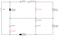
Have a look at this well behaved bookshelf design, using Visaton Drivers:
Do you notice something about the ratios of the components? Remember that crossover frequency is Root 1/LC, and impedance is Root L/C. Crossover at 3.5kHz, and phase and flatness is exemplary. It's a 2:1 ratio of course.
Now here is a well behaved 3.5 kHz Series crossover:
This has a 3:1 ratio.
See, it's adding in some bafflestep inductance and making it into a standmounter that skews the values so you can't see the pattern. BTW, you can make most stuff fit just by adjusting the red resistors. Isn't that COOL!
Have a look at this well behaved bookshelf design, using Visaton Drivers:
An externally hosted image should be here but it was not working when we last tested it.
Do you notice something about the ratios of the components? Remember that crossover frequency is Root 1/LC, and impedance is Root L/C. Crossover at 3.5kHz, and phase and flatness is exemplary. It's a 2:1 ratio of course.
Now here is a well behaved 3.5 kHz Series crossover:
An externally hosted image should be here but it was not working when we last tested it.
This has a 3:1 ratio.
See, it's adding in some bafflestep inductance and making it into a standmounter that skews the values so you can't see the pattern. BTW, you can make most stuff fit just by adjusting the red resistors. Isn't that COOL!
Attachments
I think that's purely a coincidence, as not many of my sdesigns are set to a ratio.
Later,
Wolf
That tidy 3:1 ratio is not a coincidence at all!
An externally hosted image should be here but it was not working when we last tested it.
The bookshelf combination above just happens to be so close to time aligned, within 12mm, that it works. It also has no bafflestep.
An externally hosted image should be here but it was not working when we last tested it.
This is a whole new way of designing. No surprise to me that the Forum Wizards have moved onto time aligned.
That tidy 3:1 ratio is not a coincidence at all!...
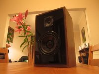
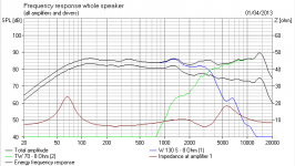
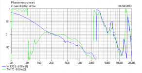
There's the speaker (pic) and there's the schematic.
How does it sound? / measure acoustically?
Looks good enough that I want to build one. It is, of course, using the drivers the same as a certain respected current design. They happen to play together nicely. Most of the lumps in the frequency response are a feature, rather than a fault. But it'll sound exactly what it is, a 12L paper cone bookshelf design with the characteristic paper sound signature and rather good lobing.
I found that equalising out the 1.4kHz lump was more trouble than it was really worth, and perhaps not even a good thing to do.
I found that equalising out the 1.4kHz lump was more trouble than it was really worth, and perhaps not even a good thing to do.
Attachments
OK- I worded that funny. It should be a coincidence in most cases, unless they targeted it that way. Typically, a ratio of parts values is not the best way to design a speaker without tradeoffs.
The reason there is no applied BSC, is likely because the woofer has a rising response towards the lowend. Without one or the other, you will have weak bass. I understand the almost-time aligned setup, and that's fine so you can use the same order of xover on both.
But- I would personally put a tweaked CR filter across the tweeter to droop the top-end unless I listen to them off-axis. This is also a tradeoff.
So- we likely have a high Q woofer to utilize the increasing lowend response into a small sealed box and still get extension without BSC applied. Sub par in terms of FR transient ripple.
Just because the BSC circuit is not used doesn't mean there is not any, and preserving acoustic phase to all ends with compromised other choices seems like a supremely misweighted design.
Later,
Wolf
...So- we likely have a high Q woofer to utilize the increasing lowend response into a small sealed box and still get extension without BSC applied. Sub par in terms of FR transient ripple.
Just because the BSC circuit is not used doesn't mean there is not any, and preserving acoustic phase to all ends with compromised other choices seems like a supremely misweighted design....
What IS this gibberish? Wolfie, there are no tricks here. It's just how it works. Make one thing different and something else gets affected. But to some extent, YOU CAN HAVE IT ALL! Series circuits are FAB! They strip filters bare.
The Visaton W130S has a Vas of 12L and a Qts of 0.47, so unless I am losing my touch, 12L is about the optimum volume for closed box so there should be NOT A WHIFF of the HORROR that is "Transient Ripple".
A dome tweeter can be done too for better dispersion, Fs correction and a tweeter zobel do much good too. After all, we can all do this stuff, it's not hard. And phase alignment is then even better as it goes. But that would add complexity and is not my interest. There are also people who think a speaker without bafflestep is compromised. Well. think again.
Achingly funny post, this, IMO. S7 retires to a safe distance, giggling...
I didn't know what the drivers were, nor did I need to click on the posted pics you put up to see them well enough. It was a practical application WAG.
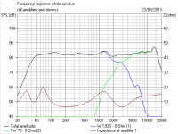
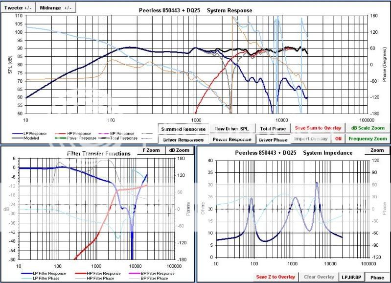
From the system plot, the design did not need BSC as it was present in a rising response on the woofer or it would not be flat- if the simulation and measurements were done properly, and there is no BSC as you stated.
From the plot of the woofer, apparently it is not a rising response, which means there is BSC present on the design. You see that 0.75mH coil? That's typically your BSC comp, whether you knew that or not.
To say there is no BSC, and have a measured FR that is flat to the knee, and not have a woofer that increses output with decreasing freq; proves that there is BSC on the design. It won't measure flat with it.
Later,
Wolf
You are nitpicking, my friend. There is off course 0.75mH plus 0.25mH of filter inductance. Making 1mH. Sort of bass curve you'd pull the speakers slightly away from the wall to get them sounding balanced. But we're not really interested in that. You get what you get with the component values.
You miss the bigger picture with the phase alignment. The +3dB bump at crossover is a FEATURE! It's constant power BUTTERWORTH rather than boring old flat LINKWITZ-RILEY, and you suddenly see what it REALLY does.
It's also interesting that Steen Duelund's ideas of always correcting driver impedance become crucial with series filters. These circuits thrive on Fs correction and Zobels. They work best time-aligned. The most interesting study I have ever done in filters. I think it might also explain why valve amps sound good too, but I digress now.
An externally hosted image should be here but it was not working when we last tested it.
You miss the bigger picture with the phase alignment. The +3dB bump at crossover is a FEATURE! It's constant power BUTTERWORTH rather than boring old flat LINKWITZ-RILEY, and you suddenly see what it REALLY does.
It's also interesting that Steen Duelund's ideas of always correcting driver impedance become crucial with series filters. These circuits thrive on Fs correction and Zobels. They work best time-aligned. The most interesting study I have ever done in filters. I think it might also explain why valve amps sound good too, but I digress now.
No- that's not 1mH on the woofer. The nodes attach differently. That still does not mean there is no BSC in the design, as you stated was the case. If that is not what you're interested in, then why did you state it as such a great thing or a feature? So the components are of a ratio- big deal.
It gives a peak at xover, wow that's cool.... Of course it will without spread factor. I'll keep my flat responses, whether BW, Bessel, or LR.
No- the Fs correction is not crucial. You do not have to have resistive load through the drivers' Fs, unless you're using a very picky tube amp. I have yet to use woofer Fs comp in any xover; either SXO or PXO. You're stating what helps in PXO design as well. Flat resistance and time alignment allow for textbook filters with the exception of resonances. It's not SXO exclusive, but neither really requires these kind of things to be great or fantastic.
You're rambling off things that are supposedly better about this design in reference to an SXO mantra- and it really is no different than if it was a PXO in terms of making it excellent. That's what I have an issue with. These are qualities that can benefit both styles of xover, regardless of any absurd ratio of parts values.
Later,
Wolf
It gives a peak at xover, wow that's cool....
Of course it will without spread factor. I'll keep my flat responses, whether BW, Bessel, or LR.No- the Fs correction is not crucial. You do not have to have resistive load through the drivers' Fs, unless you're using a very picky tube amp. I have yet to use woofer Fs comp in any xover; either SXO or PXO. You're stating what helps in PXO design as well. Flat resistance and time alignment allow for textbook filters with the exception of resonances. It's not SXO exclusive, but neither really requires these kind of things to be great or fantastic.
You're rambling off things that are supposedly better about this design in reference to an SXO mantra- and it really is no different than if it was a PXO in terms of making it excellent. That's what I have an issue with. These are qualities that can benefit both styles of xover, regardless of any absurd ratio of parts values.
Later,
Wolf
- Status
- This old topic is closed. If you want to reopen this topic, contact a moderator using the "Report Post" button.
- Home
- Loudspeakers
- Multi-Way
- Series Crossover