It started out and a refurbishment of my main speakers. They were the Larry Hughes bookshelf as described "A DIY Bookshelf Speaker" in HiFi Answers July 1978 issue. It is a closed box 17"x10"x8" using Audax HD17B25H and HD12x9D25. Both Badger Sound and Falcon Acoustics had built crossover for it. They are 30 years old and went out of business a while back. The woofer aged, but the tweeter still sounds good. I tried a few commercial boxes and found them wanting.
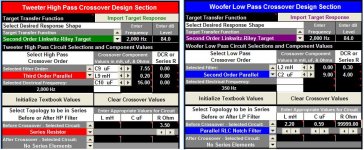
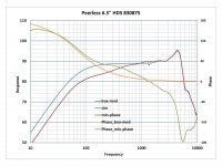
But I ended up building brand new bookshelf using the Peerless Nomex 830875 and Dayton Audio RS28A-4 in a 15 litres closed box. I will post my venture sometime when it is fully completed and auditioned at the DIY forum. Attached is the crossover and response simulation using Bagby's PCD software.


I chose closed over vented box for the faster transient response. I used a pair of aperiodic subwoofers so that the bookshelf lower bass extent is not as critical as the response character. The baffle compensation was simulated by Bagby's "Response Modeler" as outlined by Paul Carmody.
https://sites.google.com/site/undefinition/simulated-measurements
The speakers have been assembled and sound pretty good to me. I am still fine tuning and adjusting the crossover. Any critique and comment are welcome.

But I ended up building brand new bookshelf using the Peerless Nomex 830875 and Dayton Audio RS28A-4 in a 15 litres closed box. I will post my venture sometime when it is fully completed and auditioned at the DIY forum. Attached is the crossover and response simulation using Bagby's PCD software.
I chose closed over vented box for the faster transient response. I used a pair of aperiodic subwoofers so that the bookshelf lower bass extent is not as critical as the response character. The baffle compensation was simulated by Bagby's "Response Modeler" as outlined by Paul Carmody.
https://sites.google.com/site/undefinition/simulated-measurements
The speakers have been assembled and sound pretty good to me. I am still fine tuning and adjusting the crossover. Any critique and comment are welcome.
Last edited:
The box is too big for this driver. Around 6-7L would be optimal.
As for the crossover I suspect it is too midrange forwarded, but maybe you like it that way. With the relatively high number of components you used you could tame the breakup and have better phase tracking up to 5KHz. Have a look here for an inspiration: Studio-101
Ralf
As for the crossover I suspect it is too midrange forwarded, but maybe you like it that way. With the relatively high number of components you used you could tame the breakup and have better phase tracking up to 5KHz. Have a look here for an inspiration: Studio-101
Ralf
The box is too big for this driver. Around 6-7L would be optimal.
As for the crossover I suspect it is too midrange forwarded, but maybe you like it that way. With the relatively high number of components you used you could tame the breakup and have better phase tracking up to 5KHz. Have a look here for an inspiration: Studio-101
Ralf
Ralf, thank you for the feedback.
I am a little puzzle by the box size comment. First, a 6-7 litre box is unusual for a 6.5" woofer because it will be somewhat small to find a box dimension with proper baffle width. Second, the smaller box will get a much higher efficiency, a little bumpy mid bass at the expenses of transient performance. I am aware that most 6.5" closed box use 10-12 litres box. I used the "Sonic Barrier 3/4" 3-layer composite damping material" to line all the walls (not the baffle). So the effective box volume is about 11 litres (?).
What is the reason of the midrange forward and what should I do about it? The PCD shows a very uniform frequency response from 500 Hz and up and it sounds like it. I used the BSC (baffle step compensation) on woofer and the padding resistor for tweeter to get the smoothest response. I did the BSC by trial and error on the PCD software. Any better process?
I chose the Dayton Audio RS28A-A tweeter to allow me lower crossover frequency. It was first done to improve dispersion, thus the imaging. And it has the bonus of not have to worry about the woofer breakup at 5KHz when crossover low. Did I overlook something? I am familar with most of the speaker designs by Troels Gravesen. He is actually one of the reason I chose the Peerless Nomex woofer. Thank you for the link, but it is a different design. Troels used a tuned RLC to tame the woofer breakup.
I will be very happy to try it if you have specific suggestion on crossover component changes.
15L is actually very close to a box Q of 0.5 which should be fine and give you a bit more bass extension. Attached is comparison of 6L and 15L. Note that the main tradeoff will be reduced power handling.
You have a bit of a shelf between 500Hz and 3Khz which will likely make the midrange a bit more prominent. Have you turned on the target responses in PCD? to me although it is simming fairly flat, it does not look to me like your drivers are rolling off at a 4th order LR acoustic slope.
Tony.
You have a bit of a shelf between 500Hz and 3Khz which will likely make the midrange a bit more prominent. Have you turned on the target responses in PCD? to me although it is simming fairly flat, it does not look to me like your drivers are rolling off at a 4th order LR acoustic slope.
Tony.
Attachments
Last edited:
The driver you chose is optimized for a relatively small vented box, in fact 15L should be close to the optimal vented box. A closed box should be stuffed and not only lined but note also that damping material has the effect of increase the volume as seen by the driver up to 20%. Finally a Q of 0.7 has no bump at all.I am a little puzzle by the box size comment. First, a 6-7 litre box is unusual for a 6.5" woofer because it will be somewhat small to find a box dimension with proper baffle width. Second, the smaller box will get a much higher efficiency, a little bumpy mid bass at the expenses of transient performance. I am aware that most 6.5" closed box use 10-12 litres box. I used the "Sonic Barrier 3/4" 3-layer composite damping material" to line all the walls (not the baffle). So the effective box volume is about 11 litres (?).
No. He used the RLC network to flatten the response between 500Hz and 1KHz, and a RC network to tame the breakup (in parallel to the main coil). This second network cannot be simulated in PCD, something that drove me in the past away from PCD to Speaker Workshop first and then xsim.Thank you for the link, but it is a different design. Troels used a tuned RLC to tame the woofer breakup.
As Tony said, you should look at the target response in PCD, LR4 for the tweeter and a shallower response for the woofer in order to align the listening axis with the tweeter
Ralf
Tony and Ralf, thank you both for the comments.
I am at work now. I will digest them more tonight before replying.
I asked pointed questions to learn. I hope that you will not take it as argumentative.
One of the thing that I would like to improve on is the BSC for the woofer.
I am at work now. I will digest them more tonight before replying.
I asked pointed questions to learn. I hope that you will not take it as argumentative.
One of the thing that I would like to improve on is the BSC for the woofer.


No. He used the RLC network to flatten the response between 500Hz and 1KHz, and a RC network to tame the breakup (in parallel to the main coil). This second network cannot be simulated in PCD, something that drove me in the past away from PCD to Speaker Workshop first and then xsim.
Ralf
I stand corrected. I used the RL network (0.9 mh and 3 ohm parallel) for BSC to tame the rising bump between 500 Hz and 1 KHz. It is connected in series to the woofer. It seems to achieve what I want. I pad the tweeter to match the level. The price for this flat frequency response is a lower efficiency.
The RLC network that Troels used in the "Studio-101" had a narrower dip around 500 Hz. How do I tailor it for my crossover if I want to use it to replace my current series RL network?
I have the RC zobel network too which seems to do a good job flatening the impedance at higher frequency. It smooths out the response at the crossover point. The PCD seem to simulate it quite well.
I hope you don't mind but I've just done a sim with these drivers. I like to use as few components as I can get away with and came up with this:
Zuhl, thank you for taking the time to do the simulation.
I started out with something very, very similar to what you did. The simulation looked very smooth and the efficiency was high. But it sounded too forward for my taste.
After some more research, I found out that I need to account for the baffle step effect. I used Bagby's "Response Modeler" to do that and created the minimum phase FRD/ZMA. Once I did that, the bump around 1-2 KHz became obvious and explained the forward sounding result.
The posted crossover is my third iteration that include a BSC network and the tweeter is pad down more to match. I like the sound ok. Some comments still think that I may have a forwarded sound. I am all ears for suggestion.
Where did you get the driver character files? What did you use for the simulation? Unless we can afford custom made drivers like the big high end manufacturer, otherwise, the crossover is necessary to have compensation network(s) to account for the driver issues.
Last edited:
I use X-Sim for the simulation - great piece of software. I have a collection of driver files I use for sims.
If you have a forward mid then you need to increase baffle step. Sims are fine but you usually find in room tweaks necessary to get a sound you prefer and to adjust for any room acoustics. The final step should always be listening to music; though here you can get berated for suggesting such")
Here is L1 at 2.0mH:
Here is L1 at 2.5mH:
You could also increse the size of R1 if the top end became too bright as a result of changing L1.
I like what I see of that Peerless mid/bass - I may be tempted by it myself. I'd probably mate it with something like a SEAS 27TFFC though. I don't much like the look of that Dayton response.
If you have a forward mid then you need to increase baffle step. Sims are fine but you usually find in room tweaks necessary to get a sound you prefer and to adjust for any room acoustics. The final step should always be listening to music; though here you can get berated for suggesting such
Here is L1 at 2.0mH:
An externally hosted image should be here but it was not working when we last tested it.
Here is L1 at 2.5mH:
An externally hosted image should be here but it was not working when we last tested it.
You could also increse the size of R1 if the top end became too bright as a result of changing L1.
I like what I see of that Peerless mid/bass - I may be tempted by it myself. I'd probably mate it with something like a SEAS 27TFFC though. I don't much like the look of that Dayton response.
I use X-Sim for the simulation - great piece of software. I have a collection of driver files I use for sims.
I just downloaded the X-SIM and it seems like an interesting program. I particularly like the free form graphic schematic entry feature. In his original release anouncement, the author said:
bwaslo said:XSim does not yet include geometric features (such as varying mic position, baffle or boundary-bounce effects) as in Jeff Bagby's very successful "PCD" and other programs derived from it. But that is in the works, with some assistance from Jeff. There are also as yet no box-design features, but this is also planned so that full designs can be worked with using the infinite baffle data provided by vendors.
I wonder where does X-SIM stand in including the box design effects. For the mean time, I can continue to use Bagby's "Response Modeler" to modify the vendor infinite baffle data to account for the box/baffle effects.
If you have a forward mid then you need to increase baffle step. Sims are fine but you usually find in room tweaks necessary to get a sound you prefer and to adjust for any room acoustics. The final step should always be listening to music; though here you can get berated for suggesting such
Here is L1 at 2.0mH:
Here is L1 at 2.5mH:
You could also increse the size of R1 if the top end became too bright as a result of changing L1.
The forward midrange is a result of the baffle step effect not accounted for. I played with increasing L1 and C1, but could not get a smooth response.
I can get what you get in simulation if I use the vendor's infinite baffle data. I cannot agree more that "The final step should always be listening to music". That's how I found out the importance of including the baffle step compensation in the crossover simulation.
Can you explain how you "increase baffle step"?
I like what I see of that Peerless mid/bass - I may be tempted by it myself. I'd probably mate it with something like a SEAS 27TFFC though. I don't much like the look of that Dayton response.
The Dayton Audio RS28A-4 is the first metallic dome I ever tried. I like it fine so far. I am building a second set of similar bookshelf with the Vifa D27TG-35-6 soft dome. I crossover the Vifa at slightly higher frequency. I have completed the PCD design and half way in building the cabinet.
The Seas 27TFFC was on my short list of soft dome choices. I ended up with the Vifa because of availability at the time of purchase.
A picture of the assembled bookshelf. I plan to veneer with walnut finish and will start that this weekend.

Last edited:
L1 controls the amount of baffle step; C1 determines the final roll off frequency. In the x/o I did L1 at 1.7mH produces a flat response. Increasing the value of L1 increases baffle step compensation (by reducing the amount of mid frequencies on the bass driver). The other two examples at 2.0 and 2.5mH show what this does.
If you have too much mid then you need to increase the value of L1.
If you have too much mid then you need to increase the value of L1.
L1 controls the amount of baffle step; C1 determines the final roll off frequency. In the x/o I did L1 at 1.7mH produces a flat response. Increasing the value of L1 increases baffle step compensation (by reducing the amount of mid frequencies on the bass driver). The other two examples at 2.0 and 2.5mH show what this does.
If you have too much mid then you need to increase the value of L1.
How do you apply the box simulation to your FRD file? Since the XSim does not have that function, your simulation curves does not seem to show the baffle diffraction and step loss effect.
I tried your suggestion of larger L1's and removing the BSC network. It works similar to your plots that have a board 2-3 dB dip from 1-3 KHz. It seems to predict a more boomy mid bass and recessed mid range. I have not tried to mod the crossover that way yet. I am not sure I will like it better. My target is as smooth a response as possible from 500 Hz to 5 KHz. (Room effect takes over below that.)
You are the first person that I heard from who suggests that one can use L1 and C1 to control BSC. Do you have a link to a more in depth technical discussion on how this can be done. Simply increasing L1 does not seem to do it unless you do not apply box simulation. Without box simulation, the crossover simulation is useless. I am sorry to say that. What is your thought on the subject of BSC?
keilau, in practice there are very, very few xo's that actually use a separate bsc circuit. As Zuhl has been trying to explain, almost all of them use the main coil, L1, to flatten the rising response that results from the baffle step loss and then the parallel cap, C1, to shape the roll-off at the xo point. Have a look through any number of speaker projects and you should observe this to be true. A resistor in the parallel leg is also quite useful for shaping the roll-off, as well as helping to align phase as well. (btw turn the Driver Phase on in the top System Response window because you want to line those up in the xo area as well)
Of course, sometimes it's not so simple and you can't quite get a a flat response this way, so a notch filter (LCR in parallel or series) is frequently used to tame any bump(s) that might remain. Or something else, it always depends......
You should play some more in PCD to get a feel for this and/or see if you can locate some other projects that use one of your drivers and use their xo as staring points. Or go over some of the sample files that Jeff has provided with PCD as well.
Something else to note is that zobels are not a necessity. The only things that matter are that you achieve your desired acoustic and impedance targets, so if you can do it without a zobel (simple is always better and usually cheaper) then that's fine. If a zobel helps to do it too, then that's fine as well.
You might consider attaching you frd and zma files as well as a screen capture of your PCD set-up area and perhaps someone can pop those into PCD and give it a go as well. Of course, it's hoped that those files have been accurately simulated to start with. (I can't remember for sure - you may need to change the file extensions from .frd or .zma to .txt to attach them.)
keilau, in practice there are very, very few xo's that actually use a separate bsc circuit. As Zuhl has been trying to explain, almost all of them use the main coil, L1, to flatten the rising response that results from the baffle step loss and then the parallel cap, C1, to shape the roll-off at the xo point. Have a look through any number of speaker projects and you should observe this to be true. A resistor in the parallel leg is also quite useful for shaping the roll-off, as well as helping to align phase as well. (btw turn the Driver Phase on in the top System Response window because you want to line those up in the xo area as well)
You might consider attaching you frd and zma files as well as a screen capture of your PCD set-up area and perhaps someone can pop those into PCD and give it a go as well. Of course, it's hoped that those files have been accurately simulated to start with. (I can't remember for sure - you may need to change the file extensions from .frd or .zma to .txt to attach them.)
Reave, thank you for taking the time to write the lengthy response. Attached is the zip file that contains the FRD, ZMA and the PCD project files. The Dayton Audio RS28A-4 files were sent to me by Jeff Bagby in a zip named "dreydel rs28a".
View attachment peerless830875.zip
The plot below shows the difference in FRD with and without the baffle diffraction.

I found 2 bookshelf designs using the Peerless Nomex HDS 830875 woofer, Louis Coraggio's Veeper and Roman J Bednarek's Hyperion. Yes, they are the starting point of my low pass filter.
Veeper TM Monitor Speaker
Hyperion
This woofer is also used in Troel Gravesen and Joe Rasmussen's famous 2.5 ways. (All 4 are vented design. I am trading quality for quantity in using a closed box.)
Examples of the DA RS28A-4 is even easier to find. But the driver property is not. Jeff Bagby helped me out on that. (Data for RS28A-4 posted at Dayton Audio and Parts Express sites are not good.)
The fact of vented box vs. closed box and different woofer, tweeter combination makes it necessary to design the crossover myself. More importantly, for the fun of it.
After 2 years of tweaking with PCD, I found that using L1 and C1 does not work out good for me. Building one of a kind hobby speaker design. I can afford to include a BSC network if it has any benefit over the LC low pass filter.
Last edited:
Here are your drivers and crossover in X-Sim:
You can see the midrange issue you have noted.
An externally hosted image should be here but it was not working when we last tested it.
You can see the midrange issue you have noted.
Zuhl, is that with his original xo?
keilau, taking a guestimate for your driver offsets and using your frd and zma files, here's what I came up with. I found that the peak in the Peerless response at about 4500Hz was giving me problems so I put a small tanking cap (.59uF) in parallel with the main coil (2.2mH) to get a nice smooth roll-off (which requires a little bit of creativity in PCD to achieve - the large value cap equates to it not being there, not a LCR filter, just LC). You should be able to see that neither a separate bsc filter nor a zobel is necessary although if you can get it to work for you that way, it's only 1 more component than what I came up with.
The tweeter is 3rd order electrical in order to line up the phase and produce the nice reverse null.
Notice how the resistor on the parallel leg for each driver helps to both shape the FR and to align the phase.
Try those values in your version with your driver offsets. With luck the response won't change significantly but fiddle around with the values if it does.
Attachments
The problem is not the crossover method. Baffle step compensation is only correct outside a room (or if you remove your rear wall for example).After 2 years of tweaking with PCD, I found that using L1 and C1 does not work out good for me. Building one of a kind hobby speaker design. I can afford to include a BSC network if it has any benefit over the LC low pass filter.
The difference between the two woofer plots represents not lost energy, but energy that is in contention. It can get tied up in room modes before it reaches you.
The first line of defense against the baffle step is the baffle itself.
Then comes careful placement, then using the resulting response to make EQ decisions, then deciding whether the time delays have made EQ impossible or not.
Attachments
- Status
- This old topic is closed. If you want to reopen this topic, contact a moderator using the "Report Post" button.
- Home
- Loudspeakers
- Multi-Way
- The crossover for a modest DIY bookshelf speaker project