What mistakes : )
Thanks Pano then post some protests so i get it right or corrected, though can think about 2nd order where one has to be flipped and if it shall cooperate with other HT or subwoofer boxes flipping mid tweeter will get phase correct at lows for cooperation other boxes but system sum will then show flipped impulse.
Thanks Pano then post some protests so i get it right or corrected, though can think about 2nd order where one has to be flipped and if it shall cooperate with other HT or subwoofer boxes flipping mid tweeter will get phase correct at lows for cooperation other boxes but system sum will then show flipped impulse.
Attachments
")
After a few clicks, you'll get it.
The most trouble for me was to come up with a setup splitting the highs and lows, assigning each to an output. After a few minutes, I got it, and put some little stickers to identify each I/Os.
Now, I have templates I just copy over when I try something new.
Quite the nice little gizmo that miniDSP HD
Think it looks good at those scales : )
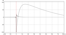
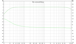
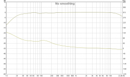
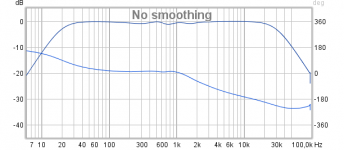
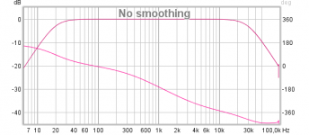
Textbook synthetics below if they can help, system stop bands are set with BW2 slopes as 20Hz and 20kHz, the last one is if XO point was pure linear phase so as to see the difference in bit lifted phase plus a hump from harsch XO.
Textbook synthetics below if they can help, system stop bands are set with BW2 slopes as 20Hz and 20kHz, the last one is if XO point was pure linear phase so as to see the difference in bit lifted phase plus a hump from harsch XO.
Attachments
Last edited:
I've been binge reading this topic the last hour and now I feel being inspired again.
Lot's of usefull information to be found in this thread.
In the past I owned a couple of B&O M70 speakers, with the filler driver. I never replaced any caps on them though, I just bought them because of the ITT dome mid, which at the time seemed an improvement over the AD02150 Philips domes I was using in my system.
I have a thing for dome mids. I now use 3" domes from the KH310 studio monitors in my system, mainly because odd order distortion is at least -80dB and at some points -100dB in the pass-band.
I would like to try and use the Harsch XO with my DCX2496, but it seems the natural response of such drivers is to small to use with these crossovers. Also, the tweeter (TW29RN-B) seems to have a too wide respone down low to make it safe enough for high listening levels. It has a natural LR12 roll-off at 700Hz...
I use a Satori MW16P-4 as a mid-woofer. In the past, I used this midwoofer and tweeter in a Kairos style setup, with the only difference that I had to use EQ to make the TW29RN response like the TW29R. This resulted in great stereo imaging. In movies for example, many times I had to turn my head around and check if nobody was closing a door behind me, while the sound came from the front speakers. Also, sounds could be heard hovering directly at the sides of my head.
With implementing the KH dome, the midrange has definately improved distortion-wise. However, the spatial effects have gone out the window. I was wondering if I could get this experience again, but with the benefit of the low distortion dome-mid.
My points of crossover currently are 650Hz LR12 between midwoofer and midrange, 2200Hz LR12 between mid and tweeter. I cannot deviate from these very much, because the midrange, well, is a midrange and has a passband response all by itself.
After reading this topic, I would think it is best to first try to equalize the units to be flat across a wide band, 2 octaves away from f-co I have read, and then try and realise the Harsch?
Would this effect power handling very badly? I run it stupid loud sometimes.
Again, thanks for the great read!
BYRTT:
Can you explain how you make the electrical XO slopes ie at FRD response to import to REW.
I have tried doing it in Rephase but the the simulated responses for the Bessel2 order does not seem to match. For bessel2 at 3000 hz I get ca minus 5 dB at 3000 - Where it should be -3. (As in your post at page 16 in this thread).
I use at "2nd order" shape with Q=0.58. Of course Butterworth works in Rephase...
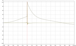
Think it looks good at those scales : )
Textbook synthetics below if they can help, system stop bands are set with BW2 slopes as 20Hz and 20kHz, the last one is if XO point was pure linear phase so as to see the difference in bit lifted phase plus a hump from harsch XO.
I'm not smart enough to even begin what to think of those measurements let alone what they mean. The reply is appreciated.
I've been binge reading this topic the last hour and now I feel being inspired again.
Lot's of usefull information to be found in this thread.
In the past I owned a couple of B&O M70 speakers, with the filler driver. I never replaced any caps on them though, I just bought them because of the ITT dome mid, which at the time seemed an improvement over the AD02150 Philips domes I was using in my system.
I have a thing for dome mids. I now use 3" domes from the KH310 studio monitors in my system, mainly because odd order distortion is at least -80dB and at some points -100dB in the pass-band.
I would like to try and use the Harsch XO with my DCX2496, but it seems the natural response of such drivers is to small to use with these crossovers. Also, the tweeter (TW29RN-B) seems to have a too wide respone down low to make it safe enough for high listening levels. It has a natural LR12 roll-off at 700Hz...
I use a Satori MW16P-4 as a mid-woofer. In the past, I used this midwoofer and tweeter in a Kairos style setup, with the only difference that I had to use EQ to make the TW29RN response like the TW29R. This resulted in great stereo imaging. In movies for example, many times I had to turn my head around and check if nobody was closing a door behind me, while the sound came from the front speakers. Also, sounds could be heard hovering directly at the sides of my head.
With implementing the KH dome, the midrange has definately improved distortion-wise. However, the spatial effects have gone out the window. I was wondering if I could get this experience again, but with the benefit of the low distortion dome-mid.
My points of crossover currently are 650Hz LR12 between midwoofer and midrange, 2200Hz LR12 between mid and tweeter. I cannot deviate from these very much, because the midrange, well, is a midrange and has a passband response all by itself.
After reading this topic, I would think it is best to first try to equalize the units to be flat across a wide band, 2 octaves away from f-co I have read, and then try and realise the Harsch?
Would this effect power handling very badly? I run it stupid loud sometimes.
Again, thanks for the great read!
In some study from past can share:
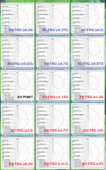
Transfer slope from LR2 to BS2 slope add a PEQ @650Hz/2200Hz Q0,58/+1,3dB.
Transfer LR2 to BW4 slope add one HP or LP BW2 @650Hz/2200Hz plus PEQs Q1,31/+4,3dB and Q0,58/-1,3dB.
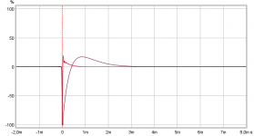
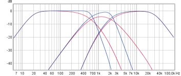
In you have system tweaked for LR2 then in theory add above electric filters into DCX2496 should transfer red traces below to blue and then set the right delays 1/650x0,5 plus 1/2200x0,5 and change all three band pass to have the same polarity.
That said think because mid band are so narrow filler like which gives a lot of traffic where all three drivers overlap each others bands think it will be hard to get everything set right because from own experience what you have at present is a very sensitive balance and a 0,1dB change for one band especially the mid can change a lot and in that LR are in phase over XO region its easyer to quality check looking for clean deep nulls switching polarity.
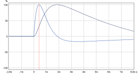
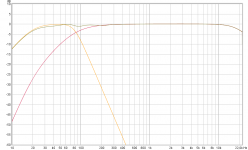
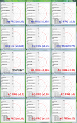
Alternative you could try harsch only at 650Hz point also because most users plus think also science experience that excess phase from XO points above say 1-2kHz area is almost impossible to sense and also your current slopes are of a mild 2nd order, below is difference between pure LR2 verse Harsch at 650Hz and LR2 at 2200Hz.
Harsch are not complete in phase over XO region so the verticals power response is bit tilted here and there and not as symmetric forward as for LR2, below example is when two summing bands are within 1/4 wavelength distance, first is LR and second is Harsch.
Attachments
Last edited:
BYRTT:
Can you explain how you make the electrical XO slopes ie at FRD response to import to REW.
I have tried doing it in Rephase but the the simulated responses for the Bessel2 order does not seem to match. For bessel2 at 3000 hz I get ca minus 5 dB at 3000 - Where it should be -3. (As in your post at page 16 in this thread).
I use at "2nd order" shape with Q=0.58. Of course Butterworth works in Rephase...
In past used JRiver DSP and ran a real electric loop with all those filters set into Jriver engine and in used soundcard beside analog I/O have pure digital I/O too then results got pretty textbook and clean. Later started use Rephase because its much faster and output as 64bit IEEE stereo or mono IR-file which when imported to REW can be manipulated in time over there beside change SPL and do all the math on "All SPL" tab, a note is use always IR with the same sample rate and if used as target curves pick same sample rate as your measurement chain use, and also if you filter measurements with windows or FDW do the same for target curves because it can sometimes make a little difference.
Over in Rephase there is not any fixed 2nd order Bessel slopes so use a LR2 and add a PEQ @XO-frq Q0,58/+1,3dB.
Hardest part is remember always to align impulses before any summing or other math, mid and tweeter bands align most often perfect using "Estimate IR delay" but the none sharp woofer band is often a little wrong aligned after that command in REW so some manual alignment is needed, the fastest way i found is after they aligned via "Estimate IR delay" then open "Overlays" window and pick its "Phase" tab where the woofer bands phase is clearly not overlaid together mid and tweeter band so now move woofers IR in programs main window for example minus 0,001ms at a time until its overlaid the other two bands. To do same for Harsch which haven't symmetric same slopes for HP verse LP you have to make one exstra temporary tweeter that have BW 4th order HP to get a reference to align woofer right.
For use in XSim export as frd-file from REW but remember first to align IR and mayby offset SPL to about 90dB levels.
I'm not smart enough to even begin what to think of those measurements let alone what they mean. The reply is appreciated.
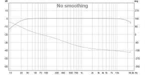
Mine graphs are synthetic textbook ones so they great as a quality check to compare your measurements.
Suggest open before measurement session and via "Limits" button at the right side up in top set other scales, for example a 10Hz to 25kHz X-axis and a +40 to+90dB Y-axis.
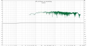
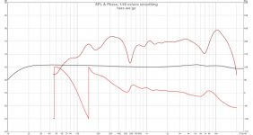
With above settings can you share before near field measurement with the window named "SPL & Phase" and ensure its legend below graph have phase ticked on because then we can compare to the third graph of mine, and wait a minute also hit "Controls" at upper right corner and push "Estimate IR Delay" maybe more than once until dialog tells delay is zero.
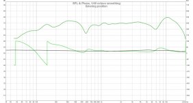
To compare second graph of mine pick "Impulse" window and with mouse inside graph window ensure setting in left top side of graph window is set to "% FS" and also use "Limits" button to tweak X and Y scales.
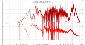
Looks scary
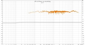
Thanks and year a bit scary but think we can filter that a bit to get a picture of more direct sound from speaker with less reflections from surroundings based on some frequence dependant time gating, so can you do it again but this time do following first, out at left side there can be many sweeps so mark that same one again and push "IR Windows" button a little left to the middle up in top and in that new dialog tick "Add frequency dependent window" and a dot in "Width in octaves" and set its number to 1/6, then push "Apply Windows" and close the dialog and you should see some much smother traces.
That said from present graph it looks your high pass section above 80Hz XO is much hotter than woofer or woofer isn't there at all or it need some many +dBs of boost or high pass section needs to be turned down a bit, what i mean is if you look at my first graph its like you only have the red trace from there where we need also to see the orange trace (woofer) show its face so they can sum together and throw the nice response seen as a gold trace. The good thing about your miniDSP is it can down the road when you get more insight maneuver its settings and features help smooth out the scary looks of response.
Last edited:
- Home
- Loudspeakers
- Multi-Way
- S. Harsch XO