Hi,
I need advice on how best to house my new WM-61A electrets. I've seen some people using long brass/plastic tubes to reduce reflections. Can anyone share their experiences on materials, lengths, thicknesses they used? Should I use a particular glue, or flexible sealant to fix the electret at the end of the wand/tube? Stuff anything else in the tube to reduce vibrations?
I think I've decided not to mod the electrets as everything I've read so far indicates that it merely increases its SPL handling capability within the same distortion levels. I will be using the mic to measure loudspeaker FR (for xover design) and don't think there is significant SPL involved to warrant the fiddly modification?
I've decided on the Wallin preamp, but don't know which version to build. I've heard that the only advantage v2 has is power consumption and v1 actually has less distortion and is easier to get parts for. Can anyone confirm?
Hi,
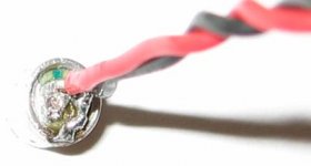
I have WM-60 insert, but I think diameter is same. I used a 1/4" ID thin brass tube 12" long. The mic capsule was a push fit in the end, and the other end is soldered to the back (cable entry end) of a metal ('gold' plated) RCA plug. Standard RCA lead can then connect to preamp.
I used preamp1 simply because I had bits on hand - it works fine. I managed to cram the preamp into an old pro microphone casing, using the original on/off switch as the gain switch. A cover screwed on where the ball used to be houses the battery and output jack, and the original XLR connector I replaced with RCA to plug the wand into. Looks strange as microphone case is in reverse, but allows standard mic clip and stand to be used.
Cheers
Hi Centauri,
Why brass? I've just bought a 6mm ID x 8mm OD aluminium tube. Off course the 6mm electret doesn't fit (why would it be that easy? ).
).
The other tube options available are iron and plastic but the alu looks nice.
Edit: Just re-read your post, and I think I see what you've done. You've used a female RCA connector on the end of the tube and used the tube to connect the ground from the electret to the RCA. So I guess there's just a single cable inside to connect the output signal right?
I also like the idea of being able to use a standard mic stand.
Did you do the electret mod?
Why brass? I've just bought a 6mm ID x 8mm OD aluminium tube. Off course the 6mm electret doesn't fit (why would it be that easy?
).The other tube options available are iron and plastic but the alu looks nice.
Edit: Just re-read your post, and I think I see what you've done. You've used a female RCA connector on the end of the tube and used the tube to connect the ground from the electret to the RCA. So I guess there's just a single cable inside to connect the output signal right?
I also like the idea of being able to use a standard mic stand.
Did you do the electret mod?
I made up two mics, with one I used a cheap computer boom mic and just replaced the cartridge and then drilled out the face of the mice to hold my WM-61A .
On my other mic, i had a shortish piece of a nice thick RCA cable that i just attached the mic to the cut end of, then i wrapped the whole thing in shrink tube, with a stiff wire added in. it lets me bend and flex the cable and it holds it's shape. I'll be using that one to hook up to my radio shack spl meter (after I get the proper mods done there)
On my other mic, i had a shortish piece of a nice thick RCA cable that i just attached the mic to the cut end of, then i wrapped the whole thing in shrink tube, with a stiff wire added in. it lets me bend and flex the cable and it holds it's shape. I'll be using that one to hook up to my radio shack spl meter (after I get the proper mods done there)
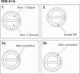
I've just been through the speakerbuilder.net description of how to mod the capsule and it appears a lot simpler than on SL's site. I'm still unsure of a couple of things, but I'm thinking that if it really is this simple, then I may as well do the mod. Here's a quick pic of the WM-61A. If someone could offer a definitive method of doing the mod, that would be great.
The SL pic shows the new connection to a tiny tab (which I can barely see on the actual capsule), and the speakerbuilder.net write-up says ...to cut the lead that connects the ground terminal to the case and dab a little silver solder to connect the other terminal to the case (where the (+) lead connects), and doesn't mention anything about shaving part of the aluminium surround, or copper ring.
Is it simply step 1, 2, 3a, then connect it to a preamp?
Attachments
Vikash said:Why brass?
So I guess there's just a single cable inside to connect the output signal right?
Did you do the electret mod?
I used brass tube so that it could be soldered to the RCA shell for the earth. A little scraping on the inside was enough to get the insert to fit.
I used twisted cables to connect the mic insert to the RCA connector, and when the connector is screwed into the shell, the tube is the earthed for shielding.
My mic capsule is standard - seems to work ok for me so far.
Cheers
Vikash said:I've just been through the speakerbuilder.net description of how to mod the capsule and it appears a lot simpler than on SL's site. I'm still unsure of a couple of things, but I'm thinking that if it really is this simple, then I may as well do the mod. Here's a quick pic of the WM-61A. If someone could offer a definitive method of doing the mod, that would be great.
The SL pic shows the new connection to a tiny tab (which I can barely see on the actual capsule), and the speakerbuilder.net write-up says ...to cut the lead that connects the ground terminal to the case and dab a little silver solder to connect the other terminal to the case (where the (+) lead connects), and doesn't mention anything about shaving part of the aluminium surround, or copper ring.
Is it simply step 1, 2, 3a, then connect it to a preamp?
I did one stock and one by your method 3a. They both work fine, but I haven't tried measuring distortion in either. You have to scrape away the one trace, but the other tiny little tab is ready to go. I just bent the end of the wire so that it soldered to the main contact with the end of the wire touching the little tab. Added a little solder there.
However, I don't see any reason why you can't just scrape away the original ground trace, solder the leads to the main terminals, then just connect a ground by physical contact to the outside surface of the electret. As long as you can maintain good contact with the surface of the capsule, this should work fine. If you run into problems, you can bridge the upper lead (as shown in your diagram) and the tiny trace.
Sheldon
Update on my measuring mic details. I put some photos etc up on my page at http://members.optusnet.com.au/~ggoodacre/Centauri/diy/mic.html
Cheers
Cheers
I've got my first mic finished and it looks good. It sure isn't easy working with those tiny capsules! I want to get a moded one working next (well I've already tried and cocked two capsules up so far).
To test it, I connected the mic to my sound card which which has a +20db gain on the mic input, and there was a lot of hiss (Hercules GT XP). Are these DIY premaps much better? I would like to use the mic for some home studio recordings as well, and don't know whether the Wallin preamp will be usable for such a task?
To test it, I connected the mic to my sound card which which has a +20db gain on the mic input, and there was a lot of hiss (Hercules GT XP). Are these DIY premaps much better? I would like to use the mic for some home studio recordings as well, and don't know whether the Wallin preamp will be usable for such a task?
Good job on the mic - the brass tube makes things easier.
I would think most of the hiss would be coming from the mic capsule electronics. The use of an external preamp (such as Eric's) will improve this as the capsule will have a higher operating voltage than what is provided by the sound card. Mods to the capsule itself can further reduce this, but the gain provided by these mods may not be fully realised if still being powered by the sound card mic preamp.
Cheers
Hi Vikash,
Have you used one of the linkwitz modded capsules with the Wallin preamp II??
I have a wallin preamp II which I made a while ago, it works really well with an un-modded capsule, but I'm a bit suspicious that it isn't as good with a modded one. The gain seems to be a bit lower, and subjectively (testing by talking into it whilst wearing headphones..... not great) it seems to distort a bit...
I've tested it's connections and I'm pretty sure my soldering is sound, however looking at the linkwitz site again, I'm wondering if there is any mod required to the preamp to get it to work properly......
Tony.
Thanks Vikash,
I thought I better ask the question, as I wasn't sure if maybe I toasted the capsules or whether the mod changed the voltage (ie +ve and -ve) requirements of the capsule (though if that were the case I guess it wouldn't work at all).
admittedly when I first made my preamp I had a major problem with gain and distortion which turned out to be a bad connection on the earth of my mic rca jack..... so it is possible that my soldering is just not up to scratch (it is really hard soldering to that tiny little tab on the edge of the capsule).... The second mic I tried is definitely an improvement so maybe I should keep trying (still have about 6 left )
Tony.
I thought I better ask the question, as I wasn't sure if maybe I toasted the capsules or whether the mod changed the voltage (ie +ve and -ve) requirements of the capsule (though if that were the case I guess it wouldn't work at all).
admittedly when I first made my preamp I had a major problem with gain and distortion which turned out to be a bad connection on the earth of my mic rca jack..... so it is possible that my soldering is just not up to scratch (it is really hard soldering to that tiny little tab on the edge of the capsule).... The second mic I tried is definitely an improvement so maybe I should keep trying (still have about 6 left
)Tony.
Bit disturbing
Hi Vikash,
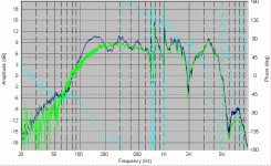
I wasn't happy with the freq response graphs I was getting from my testing (they were rolling off at 200Hz when they shouldn't really have started till about 100Hz, based on my sims), so I hooked up an unmodified capsule to my wallin preamp II, and there are some very big differences!!!
1. the gain with the unmodified capsule is much higher (went from about 2000 on the speaker workshop VU meter to 9000 with the same drive voltage on the speaker.
2. the distortion seems to be much lower (plots are much cleaner)
3. the low freq response seems to be not rolling off, though I have some very big dips that weren't there with the modded capsule.... Might need to try another capsule again!!! I had some previous measurements which didn't have these dips..
So what I'm not sure about is whether it is the preamp doesn't like the modded capsules, or whether my modding is damaging them.
One thing though... when I turn on my preamp with the modded capsule in high gain mode, the led blips then goes off, then comes on again for about a second. With the unmodded capsule it just comes on for about two seconds.... bit weird.
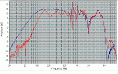
here is a comparison both of the same speaker in a completely undamped box (the nastyness at around 700Hz is rear wall reflections, I think as the length of a wavelength at the freq is exactly half the depth of the cabinet... putting some foam on the rear wall damps this quite a lot..
Tony.
edit: forgot to say the yellow (green????) plot is with the modded capsule. (I'm red green colour blind).... Oh and the graphs are not smoothed at all.
Hi Vikash,
I wasn't happy with the freq response graphs I was getting from my testing (they were rolling off at 200Hz when they shouldn't really have started till about 100Hz, based on my sims), so I hooked up an unmodified capsule to my wallin preamp II, and there are some very big differences!!!
1. the gain with the unmodified capsule is much higher (went from about 2000 on the speaker workshop VU meter to 9000 with the same drive voltage on the speaker.
2. the distortion seems to be much lower (plots are much cleaner)
3. the low freq response seems to be not rolling off, though I have some very big dips that weren't there with the modded capsule.... Might need to try another capsule again!!! I had some previous measurements which didn't have these dips..
So what I'm not sure about is whether it is the preamp doesn't like the modded capsules, or whether my modding is damaging them.
One thing though... when I turn on my preamp with the modded capsule in high gain mode, the led blips then goes off, then comes on again for about a second. With the unmodded capsule it just comes on for about two seconds.... bit weird.
here is a comparison both of the same speaker in a completely undamped box (the nastyness at around 700Hz is rear wall reflections, I think as the length of a wavelength at the freq is exactly half the depth of the cabinet... putting some foam on the rear wall damps this quite a lot..
Tony.
edit: forgot to say the yellow (green????) plot is with the modded capsule. (I'm red green colour blind).... Oh and the graphs are not smoothed at all.
Attachments
hmmmmmm
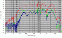
I decided to try an experiment... I wodered if reversing the polarity on the modified mic capsule would make any difference... after doing this the freq response curve was much more like the unmodified capsule, however when I changed it back again it was still giving similar curves.... note that I didn't re-solder on the capsule itself, I cut the lead back about 10cm and made the changes there.
what I have concluded.....
1. reversing the polarity of the modded capsule reduces the distortion and gives slightly more gain
2. the unmodified capsule has roughly 9db more gain than the modified one!!
3. There was something screwy going on with the modded mic initially, I guess pulling it out has made the solder joint better.....
I'm starting to think that the linkwitz mod enables the mic to handle higher spl's simply by reducing the gain..... for my use I think I'll stick with the unmodified capsule, as I really need to drive the speakers excessively loud in order to overload it at 1M.
It is still possible that I've screwed something up, so if others want to try and post results I'd be interested..... now I just have to sort out what is causing the huge dip in my response curve at around 220 Hz
red plot is unmodified capsule
yellow plot is modded capsule connected with reverse polarity (ie mic case connected as signal)
blue plot is modded capsule normal priority (ie mic case connected to sheild)
Tony.
Attachments
sucess at last
Well after getting extremely frustrated, testing everything in site testing my vifa 10" drivers and getting an almost identical freq response curve I decided something was very very wrong....
I soldered up a new mic capsule and tried it out (non modified) and wow what a difference. I'm VERY pleased with the result (still has horrible rear of cabinet reflections but that's easy to deal with)...
This actually looks like I had expected from the sims yayyyy
I'm going to stick with this mic now and not play around with the mods anymore!!!
edit: just thinking about it, both mics had virtually the same response (modded and unmoded) with a weird series of dips and peaks. To save soldering onto the mics directly multiple times, I cut the lead at about 10cm and soldered (and used insulation tape) it to the longer lead... is it possible that the effect I was seeing was due to capacitance I introduced by soldering the lead? There were two bear wires soldered together and held tightly with a bit of insulation tape in between... I'm just thinking it is highly unlikely that the mics would both cook in exactly the same way, and this was the thing that I changed this morning (the modded mike started behaving differently after I connected it up this way, It's previous response was not great but better than that).
I think I'll get the modded mike and solder it directly to an rca plug and see what changes
Tony.
Well after getting extremely frustrated, testing everything in site testing my vifa 10" drivers and getting an almost identical freq response curve I decided something was very very wrong....
I soldered up a new mic capsule and tried it out (non modified) and wow what a difference. I'm VERY pleased with the result (still has horrible rear of cabinet reflections but that's easy to deal with)...
This actually looks like I had expected from the sims
yayyyy I'm going to stick with this mic now and not play around with the mods anymore!!!
edit: just thinking about it, both mics had virtually the same response (modded and unmoded) with a weird series of dips and peaks. To save soldering onto the mics directly multiple times, I cut the lead at about 10cm and soldered (and used insulation tape) it to the longer lead... is it possible that the effect I was seeing was due to capacitance I introduced by soldering the lead? There were two bear wires soldered together and held tightly with a bit of insulation tape in between... I'm just thinking it is highly unlikely that the mics would both cook in exactly the same way, and this was the thing that I changed this morning (the modded mike started behaving differently after I connected it up this way, It's previous response was not great but better than that).
I think I'll get the modded mike and solder it directly to an rca plug and see what changes
Tony.
Attachments
Well I'm glad you got it sorted. I butchered the only electret I've actually wired when modding it: http://www.vikash.info/audio/measurement_mic/
It took me many attempts to make the connections, and the soldering work was aweful. But still not problems with the electret working first time with the preamp.
I'm going to do some meauring today and will report how it goes. Thanks for posting your findings, hopefully it will be of help.
It took me many attempts to make the connections, and the soldering work was aweful. But still not problems with the electret working first time with the preamp.
I'm going to do some meauring today and will report how it goes. Thanks for posting your findings, hopefully it will be of help.
- Status
- This old topic is closed. If you want to reopen this topic, contact a moderator using the "Report Post" button.
- Home
- Loudspeakers
- Multi-Way
- Measurement mic/preamp questions