This is a build thread for the as yet unfinished speaker I have dubbed "Hi-Marks." A 2-way consisting of Markaudio Alpair 10.2 and Hi-Vi RT1.3WE Isodynamic Tweeter.
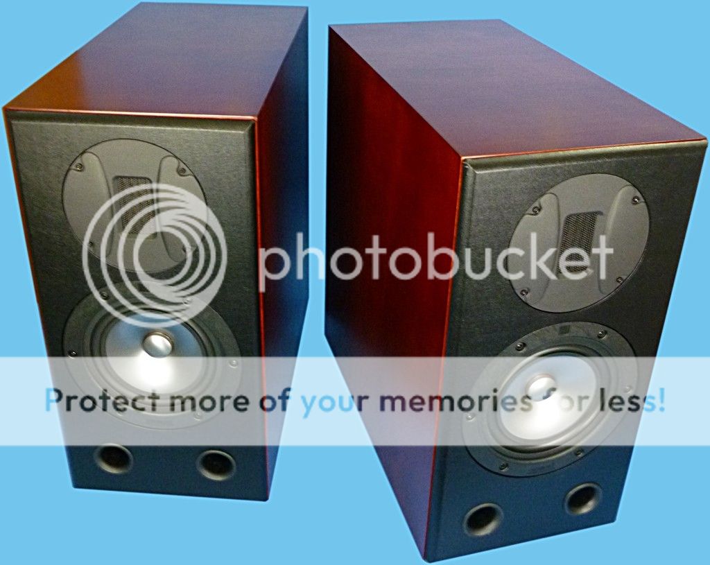
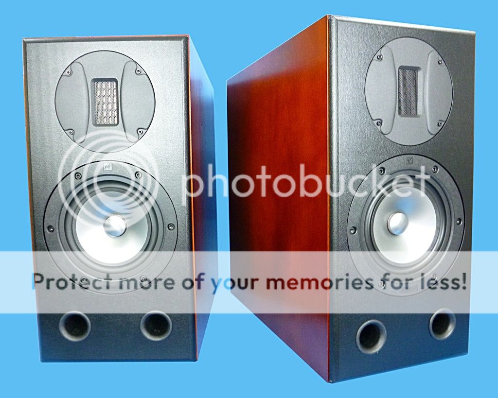
The speakers are currently complete except for the crossover. Here are some photos:
I'm currently working on the external crossover and greatly appreciate all of the generous help that DIYAudio members have provided me with the process.")
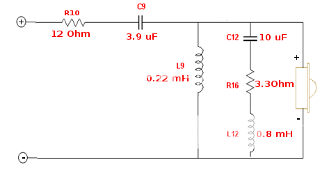
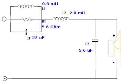
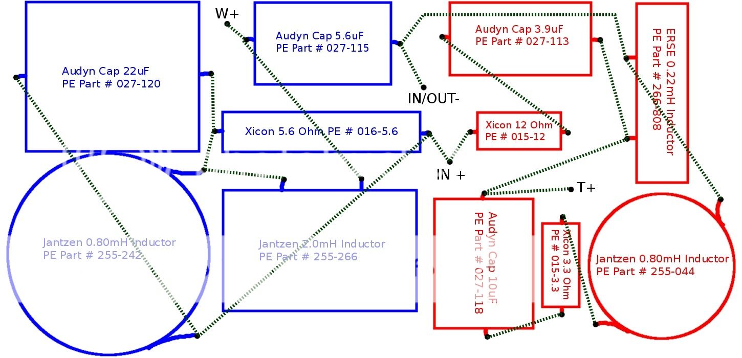
Here is the current crossover design:
Tweeter section:
Woofer section:
Wiring layout (dashed lines represent wires underneath the board. board is 7.25" x 3.437" approx.):
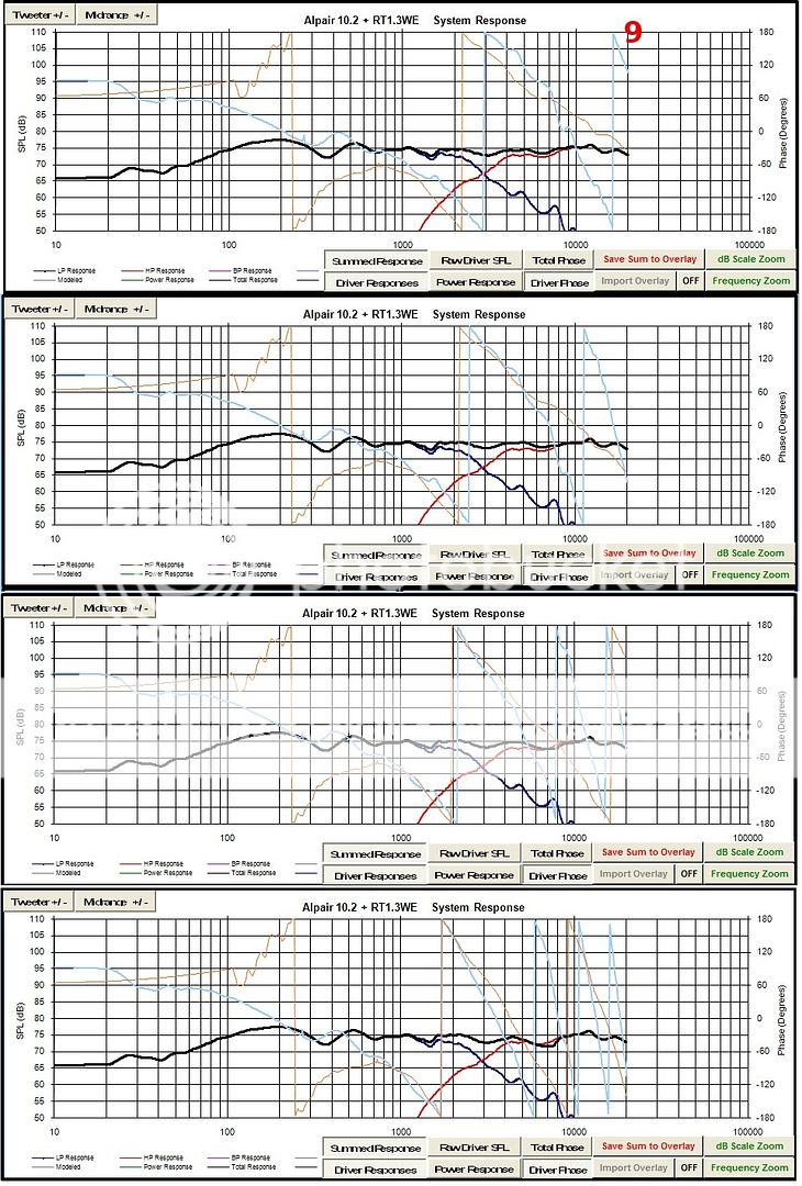
Simulated frequency response (image shows the system response at 0 degrees, 2.86 degrees, 5.71 degrees and 8.53 degrees off axis vertically, respectively down the page):
External Crossover bill of materials:
Desc. | Parts Express Part # | Qty | Price ea. | Total
Hammond 1591ESBK ABS Project Box Black 7.5" x 4.4" x 2.4" Part # 320-718 2 $7.46 $14.92
3.3 Ohm 5W Resistor Wire Wound 5% Tolerance Part # 015-3.3 2 $0.68 $1.36
12 Ohm 5W Resistor Wire Wound 5% Tolerance Part # 015-12 2 $0.68 $1.36
5.6 Ohm 10W Resistor Wire Wound 5% Tolerance Part # 016-5.6 2 $0.64 $1.28
Audyn Cap Q4 10uF 400V MKP Metalized Polypropylene Foil Crossover Capacitor Part # 027-118 2 $4.31 $8.62
Audyn Cap Q4 22uF 400V MKP Metalized Polypropylene Foil Crossover Capacitor Part # 027-120 2 $8.57 $17.14
Audyn Cap Q4 5.6uF 400V MKP Metalized Polypropylene Foil Crossover Capacitor Part # 027-115 2 $2.99 $5.98
Audyn Cap Q4 3.9uF 400V MKP Metalized Polypropylene Foil Crossover Capacitor Part # 027-113 2 $2.29 $4.58
Jantzen Audio 0.80mH 20 AWG Air Core Inductor Crossover Coil Part # 255-044 2 $7.28 $14.56
Jantzen Audio 0.80mH 18 AWG Air Core Inductor Crossover Coil Part # 255-242 2 $9.14 $18.28
Jantzen Audio 2.0mH 18 AWG Air Core Inductor Crossover Coil Part # 255-266 2 $14.12 $28.24
ERSE 0.22mH 18 AWG Perfect Layer Inductor Crossover Coil Part # 266-808 2 $5.39 $10.78
Parts Express Dual Binding Post 1 Red 1 Black Part # 090-475 2 $3.88 $7.76
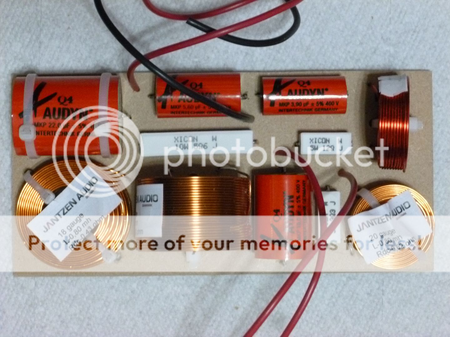
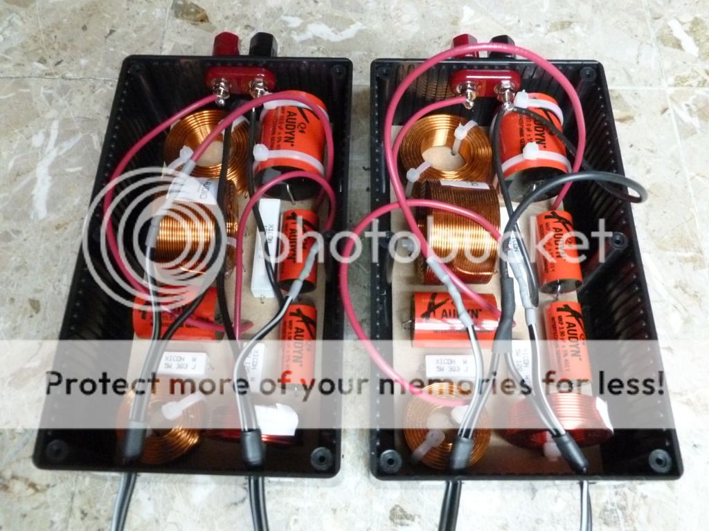
A bare completed crossover board, top and bottom:
The completed crossovers in their boxes, sans lids:
Specs and older updates:
Target crossover frequency is around 3Khz.
Cabinet volume is approximately 0.6 cubic foot / 17 litres with internal dimensions of approximately 13.7" H x 5.75" W x 13.3" D. The sides and top/bottom are 1-1/8" thick consisting of 3/4" void-free baltic birch ply and 3/8" veneered particleboard. The front baffle is just the 3/4" BB ply but it is relatively narrow and supported on all edges so it should be strong. There is no bracing as that would probably be overkill for such a relatively small cabinet with thick, rigid walls and the goal is to keep this relatively simple on the woodworking front.
The tuning is 41 Hz with two 1" ports PE # 260-470. Cut to 3.34" long each. In addition to the 3.34" port length I allowed a little extra (approximately 1/4") to account for the flare.
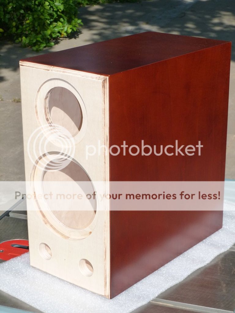
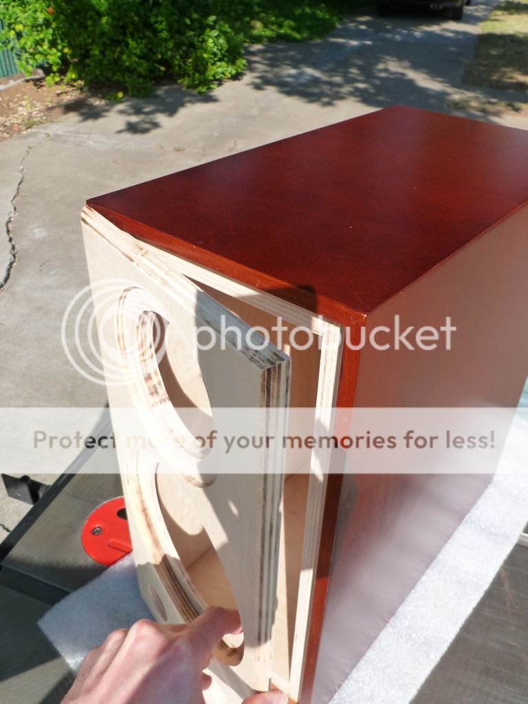
I have made some progress on the cabinets.
Photos:
The current plan is to finish the front baffle with leather texture black vinyl, install 1/2" blue cotton insulation, glue the baffles in, mount the drivers and two sets of binding posts per speaker. I plan on an external passive crossover.
The next step after that will be to measure the drivers in the cabinets in order to generate .frd files for crossover design. For the impedance .zma files I'll probably just use the manufacturer's data per Paul Carmody's guide.
Once I get my crossover design together over the next couple of weeks, I'd appreciate all of your opinions and help on it.
The speakers are currently complete except for the crossover. Here are some photos:
I'm currently working on the external crossover and greatly appreciate all of the generous help that DIYAudio members have provided me with the process.
Here is the current crossover design:
Tweeter section:
Woofer section:
Wiring layout (dashed lines represent wires underneath the board. board is 7.25" x 3.437" approx.):
Simulated frequency response (image shows the system response at 0 degrees, 2.86 degrees, 5.71 degrees and 8.53 degrees off axis vertically, respectively down the page):
External Crossover bill of materials:
Desc. | Parts Express Part # | Qty | Price ea. | Total
Hammond 1591ESBK ABS Project Box Black 7.5" x 4.4" x 2.4" Part # 320-718 2 $7.46 $14.92
3.3 Ohm 5W Resistor Wire Wound 5% Tolerance Part # 015-3.3 2 $0.68 $1.36
12 Ohm 5W Resistor Wire Wound 5% Tolerance Part # 015-12 2 $0.68 $1.36
5.6 Ohm 10W Resistor Wire Wound 5% Tolerance Part # 016-5.6 2 $0.64 $1.28
Audyn Cap Q4 10uF 400V MKP Metalized Polypropylene Foil Crossover Capacitor Part # 027-118 2 $4.31 $8.62
Audyn Cap Q4 22uF 400V MKP Metalized Polypropylene Foil Crossover Capacitor Part # 027-120 2 $8.57 $17.14
Audyn Cap Q4 5.6uF 400V MKP Metalized Polypropylene Foil Crossover Capacitor Part # 027-115 2 $2.99 $5.98
Audyn Cap Q4 3.9uF 400V MKP Metalized Polypropylene Foil Crossover Capacitor Part # 027-113 2 $2.29 $4.58
Jantzen Audio 0.80mH 20 AWG Air Core Inductor Crossover Coil Part # 255-044 2 $7.28 $14.56
Jantzen Audio 0.80mH 18 AWG Air Core Inductor Crossover Coil Part # 255-242 2 $9.14 $18.28
Jantzen Audio 2.0mH 18 AWG Air Core Inductor Crossover Coil Part # 255-266 2 $14.12 $28.24
ERSE 0.22mH 18 AWG Perfect Layer Inductor Crossover Coil Part # 266-808 2 $5.39 $10.78
Parts Express Dual Binding Post 1 Red 1 Black Part # 090-475 2 $3.88 $7.76
A bare completed crossover board, top and bottom:
The completed crossovers in their boxes, sans lids:
Specs and older updates:
Target crossover frequency is around 3Khz.
Cabinet volume is approximately 0.6 cubic foot / 17 litres with internal dimensions of approximately 13.7" H x 5.75" W x 13.3" D. The sides and top/bottom are 1-1/8" thick consisting of 3/4" void-free baltic birch ply and 3/8" veneered particleboard. The front baffle is just the 3/4" BB ply but it is relatively narrow and supported on all edges so it should be strong. There is no bracing as that would probably be overkill for such a relatively small cabinet with thick, rigid walls and the goal is to keep this relatively simple on the woodworking front.
The tuning is 41 Hz with two 1" ports PE # 260-470. Cut to 3.34" long each. In addition to the 3.34" port length I allowed a little extra (approximately 1/4") to account for the flare.
I have made some progress on the cabinets.
Photos:
The current plan is to finish the front baffle with leather texture black vinyl, install 1/2" blue cotton insulation, glue the baffles in, mount the drivers and two sets of binding posts per speaker. I plan on an external passive crossover.
The next step after that will be to measure the drivers in the cabinets in order to generate .frd files for crossover design. For the impedance .zma files I'll probably just use the manufacturer's data per Paul Carmody's guide.
Once I get my crossover design together over the next couple of weeks, I'd appreciate all of your opinions and help on it.
Last edited:

Hi Scott, Once I have the frd files for my in-cabinet driver response plus the zma from manufacturer's data, I planned to use Jeff Bagby's Passive Crossover Designer spreadsheet. Loudspeaker Design Software
Edit ; Oh, I just realized you probably meant a digital crossover using the computer's sound card. I'm not sure I want to get into that. But I will check out the options.
Edit ; Oh, I just realized you probably meant a digital crossover using the computer's sound card. I'm not sure I want to get into that.
But I will check out the options.
Last edited:
Edit ; Oh, I just realized you probably meant a digital crossover using the computer's sound card.
Yup!
Just using two channels for a single loudspeaker to listen to the effects in mono.
Crossover optimization and DIY loudspeaker measurement
Not tried it, but it might work for you.
If you need a cheap calibrated mic - this is the least expensive: Dayton Audio iMM-6.
To MOD's.. for some reason I'm not getting right-click in either reply box. Makes posting a link a royal pain in the @ss!
Not tried it, but it might work for you.
If you need a cheap calibrated mic - this is the least expensive: Dayton Audio iMM-6.
To MOD's.. for some reason I'm not getting right-click in either reply box.
Makes posting a link a royal pain in the @ss!
Last edited:
To MOD's.. for some reason I'm not getting right-click in either reply box.
Seems to be working again!
I bought a Dayton UMM-6 for myself last Christmas and I'm fairly familiar with REW so I'll use that. I don't think I need a capacitor on the tweeter to measure as I can set the start frequency in REW, maybe 2500 Hz although in the tooltip it says "sweep lowest frequency is half the start frequency" so maybe I better try 5000Hz. Not sure if that will work all right as the measurement data would be wrong below the start frequency but it would be wrong with a cap on there too.....
More on the above, I see on the manufacturer's data sheet for the Rt1.3WE that there is response information down to 1K on their graph. So maybe a 2K start or 3K start frequency (corresponding to 1K and 1.5K respectively) for the measurement sweep in REW would be OK at low volume levels. I hope.
If you define "low", maybe the system could be better calibrated.More on the above, I see on the manufacturer's data sheet for the Rt1.3WE that there is response information down to 1K on their graph. So maybe a 2K start or 3K start frequency (corresponding to 1K and 1.5K respectively) for the measurement sweep in REW would be OK at low volume levels. I hope.
As I read, REW is not able to do the "gating" or "subtract flight time" so it's not right software for the duty. Unless you put speakers in an anechoic room
As I read, REW is not able to do the "gating" or "subtract flight time" so it's not right software for the duty. Unless you put speakers in an anechoic room
You can get a "gated" measurement with REW: Loudspeaker measurements
However I think close mic on the driver would eliminate room interference. I am thinking of facing the speaker up and hanging the mic over it. Although I don't know if I'd lose baffle step info by close mic'ing.
I bought a Dayton UMM-6 for myself last Christmas and I'm fairly familiar with REW so I'll use that. I don't think I need a capacitor on the tweeter to measure as I can set the start frequency in REW, maybe 2500 Hz although in the tooltip it says "sweep lowest frequency is half the start frequency" so maybe I better try 5000Hz. Not sure if that will work all right as the measurement data would be wrong below the start frequency but it would be wrong with a cap on there too.....
Just make sure its 2.83 volts and at or above 800 Hz.
Planars aren't real robust thermally (at all; very similar to a fuse in fact), but their physical operation limits excursion better than just about any other tweeter design. Note: the thermal problem is really only a problem with people trying to solder to their leads, NOT from generating an impulse measurement. The only other real problem is from something like a high transient "spike" (like from turning on the amplifier).
Note that when gating, you are loosing information a few octaves above your gate freq. before you are back to more detail in the measurement. (..it's not unlike "smoothing" for a couple octaves above the gate freq.).
Finally, note that you should be able to use the digital crossover and measure with that same software at the same time.. that's a HUGE benefit with prototyping.
Note that when gating, you are loosing information a few octaves above your gate freq. before you are back to more detail in the measurement. (..it's not unlike "smoothing" for a couple octaves above the gate freq.)
So you recommend not bothering with the gating? I could avoid most of the floor bounce effect (I think) by pointing the speaker up and suspending the mic.
So you recommend not bothering with the gating? I could avoid most of the floor bounce effect (I think) by pointing the speaker up and suspending the mic.
I usually gate for a "sweep", but it's relative to my closest reflection. If you are doing it on the floor "facing up", then make sure there is plenty of sound absorption around the loudspeaker (..and of course it's best if the floor is carpeted). IF you are using an MLS "realtime" signal/test then don't worry about the gate. Here is a good video of Wayne doing such a test to find vertical nulls:
http://www.diyaudio.com/forums/mult...ce-vertical-polar-response-4.html#post2038050
Make sure however that when you are looking for your baffle-step compensation pass-band, that you are measuring it OFF the floor.
More on the above, I see on the manufacturer's data sheet for the Rt1.3WE that there is response information down to 1K on their graph. So maybe a 2K start or 3K start frequency (corresponding to 1K and 1.5K respectively) for the measurement sweep in REW would be OK at low volume levels. I hope.
You need to 'extend the tail' in Response Modeler to fix that.
Later,
Wolf
PS- if you want the 1.3 raw files, I can send them to you in an e-mail. PM me your addy...
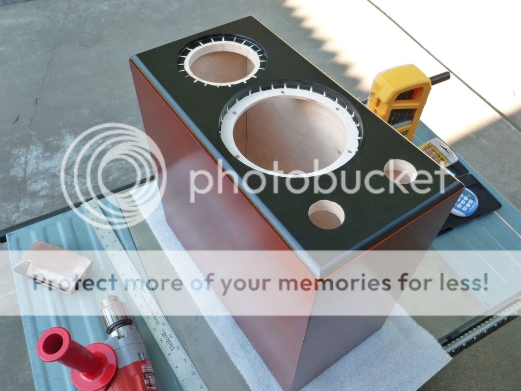
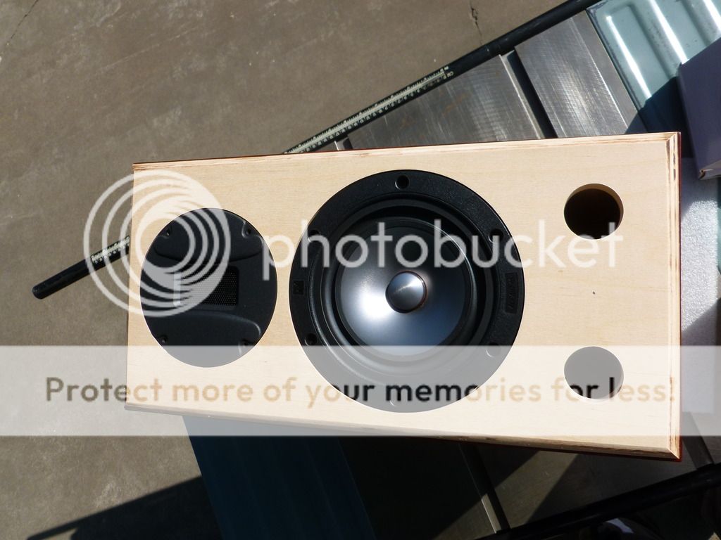
Today's update - finished the vinyl wrap on both baffles. Can't see the leather texture in the photo. Also finished drilling the 1/4" holes around back for four sets of binding posts (PE # 091-1245).
I'll order the port tubes, gorilla glue and binding posts from PE now. I initially was going to make do and order everything together (crossover parts) to save a few bucks but I think it might be better to finish assembling the speaker before doing anything at all on the measurement front.
I did simm the impedance files for both drivers already, attached. I looked at the manufacturer's spec sheet for RT1.3WE but it didn't look valid as it shows an impedance of about 1 ohm in their chart, so I used Wolf's impedance measurement for the RT1.3 which uses the same element. Should be good enough.
I used SplTrace to get the data from the Alpair's spec sheet then simmed it in Response Modeler, using the controls to get my in-box simulation to match up to the upper frequencies on my traced data.
I then extracted minimum phase from both the tweeter and Alpair's files, the end result is what you see in the attachments.
The frequency response files will come later as I've decided to do actual measurements in-cabinet instead of simm'ing those.
Attachments
Last edited:

So you recommend not bothering with the gating? I could
avoid most of the floor bounce effect (I think) by pointing
the speaker up and suspending the mic.
Recording floor bounce doesn't do any harm to design
a XO filter in the mid/high range. Proper design accounts
for horizontal sound behavior too and you will do that easier
by arranging measurements traditionally. It is important to know
where your speakers will stand in the future so you know how
to voice it properly.
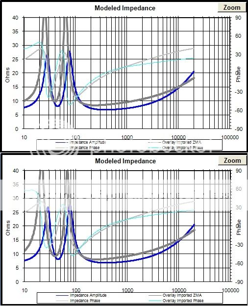
I noticed that R. Carpenter's TS measurements varied quite a bit from MarkAudio's spec sheet so I re-simmed with Carpenter's data. It did make some difference (see the dark gray bold lines in each picture) but I think it's close enough around the crossover frequency (2.5K to 3K area) that it should be OK either way.
I noticed that R. Carpenter's TS measurements varied quite a bit from MarkAudio's spec sheet
T/S parameters are not scalar they are curves. Were you pick the numbers off the curve determines what you get. The kit normally used by us diyers is usually different than factory. I use factory numbers for sims. They usually produce box designs that are closer to what you get when you build them.
dave
I use factory numbers for sims. They usually produce box designs that are closer to what you get when you build them.
Thanks Dave, sounds like I'm on the right track then. I've always read fellows complaining about how far off the actual TS parameters are (other drivers) which made me think about second guessing this but I have a bit more confidence than that in Mark. Thanks.
- Status
- This old topic is closed. If you want to reopen this topic, contact a moderator using the "Report Post" button.
- Home
- Loudspeakers
- Multi-Way
- Ben's "Hi-Marks" Fullranger + Isodynamic Tweeter 2-Way Build Thread