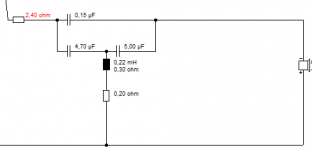
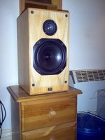
I am in the process of rebuilding my Barry Hughes' bookshelf (HiFi Answers July 1978). The original crossover was the Falcon Acoustics 21B. The high pass section for the Audax HD12x9D25 has the following components:
R2=2.4ohm (series dropping resistance)
L3=0.22mH
C2=4.7uF
C3=5 uF
I would like to change the HF section to acoustic Butterworth. I found some information on the KEF 104aB and the transformation equations in Martin Colloms book, "High Performance Loudspeakers", Pentech Press, 1980. The Falcon crossover is reasonably close to the KEF 104 values. But Martin left out some steps in his book, making the transformation from the Falcon 21B to acoustic Butterworth.
The C2 and C3 above is equivalent to the C1 and C2 in Fig-15 or Martin's book. Martin left out how to determine the value of C3 which is series with the coil. The aB component values in Fig-17 is possible using the equations in Fig-16 only if the C3 value in Fig-15 is negative!
Anyone can point me to a reference of acoustic Butterworth transformation that actually works? Many thanks.


If I correctly understand the whole concept of the aB crossover, what you need to do is first measure your drivers very carefully. Once that's done, you can use one of the several simulation programs to simulate your crossover to adjust the actual response of the drivers to the slopes you want....
Starting with an existing crossover (KEF 104ab) but using different drivers isn't going to get you closer to your goal. The layout of the parts is specific for the drivers, and that B200 was never available separately....
Starting with an existing crossover (KEF 104ab) but using different drivers isn't going to get you closer to your goal. The layout of the parts is specific for the drivers, and that B200 was never available separately....
If I correctly understand the whole concept of the aB crossover, what you need to do is first measure your drivers very carefully. Once that's done, you can use one of the several simulation programs to simulate your crossover to adjust the actual response of the drivers to the slopes you want....
Starting with an existing crossover (KEF 104ab) but using different drivers isn't going to get you closer to your goal. The layout of the parts is specific for the drivers, and that B200 was never available separately....
Can you be more specific about which simulation program can handle the acoustic Butterworth topology? I am not aware of any.

I start with the Falcon 21B crossover which was specifically designed for the Audax tweeter that I use. But it is a third order Butterworth, but NOT acoustic Butterworth.
Thank you for trying anyway.
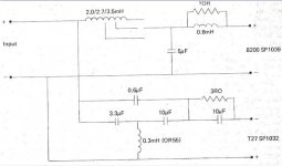
I have had a bash at this sort of KEF acoustic Butterworth thing in the past. KEFs notch is based on a 1.2kHz Fs for the T27. And there are two ways of adding the damping. 220R in series, or overall 0.55R in the shunt arm.
I was using a Morel CAT 298 which has a steep Fs resonance around 1kHz.
I can't say it sounded particularly good. In fact my analysis showed that it works more like a first order with LCR Fs notch than a third order with Fs notch. Very bright sound.
It was the very devil to model: Downloads
I had to go by the phase response on the tweeter to make sense of it. Your Audax tweeter seems to have a 15 ohm peak at 800Hz. FWIW, I got 180uF and 0.5 ohm along with 0.22mH for 800Hz LCR notch with a Q of 2, which may be a start point for KEF's way of calculating it. Some miscellaneous KEF stuff along with my guess on your modification to AB.
Do no harm to just add a 0.15uF and see what it does!
An externally hosted image should be here but it was not working when we last tested it.
An externally hosted image should be here but it was not working when we last tested it.
I was using a Morel CAT 298 which has a steep Fs resonance around 1kHz.
I can't say it sounded particularly good. In fact my analysis showed that it works more like a first order with LCR Fs notch than a third order with Fs notch. Very bright sound.
It was the very devil to model: Downloads
I had to go by the phase response on the tweeter to make sense of it. Your Audax tweeter seems to have a 15 ohm peak at 800Hz. FWIW, I got 180uF and 0.5 ohm along with 0.22mH for 800Hz LCR notch with a Q of 2, which may be a start point for KEF's way of calculating it. Some miscellaneous KEF stuff along with my guess on your modification to AB.
Do no harm to just add a 0.15uF and see what it does!
Attachments
Steve, thank you for taking the time to write. Have more questions.
The first step of transformation is the replace the HF coil with a LRC notch filter based on the tweeter's resonant frequency. Right?
Do you know what is the file format for frequency and impedance reponses of the BoxSim program? I already downloaded it and will extract the files later. The Visaton website said "Import of frequency and impedance response from many standard measuring programs (e.g. ATB, Arta, JustOct)". I do not know any of these programs. I use FRD and ZMA files to represent the drivers that I use. They are popular in the US.
TBH, I hardly know what I am talking about sometimes. I am quite intuitive about my methods.
With Boxsim, I followed the phase with my Morel Cat 298 1kHz Fs adjustment:
The Fs notch seems to be acting around 900Hz, which seemed to work. You often don't apply a notch exactly at the peak, because it's affected by slopes.
I possibly could have worked harder at attenuation on the tweeter to get it sounding right. I am known to dislike soft-dome tweeters in general.
I'd actually like to hear more about these Barry Hughes Bookshelf speakers. I kinda know how to get most of them sounding good. Might be a particular filter or choice of drive units.
For 8" bass, I like this sort of design, with third or fourth order tweeter 3kHz filter. But am open to some series crossover and second order designs, which need more slope adjustment. As AllenB seems to be saying, second or third order works sufficiently steeply that Fs really isn't an issue, being 20-40 dB down in reality, and hardly worth worrying about.
With Boxsim, I followed the phase with my Morel Cat 298 1kHz Fs adjustment:
An externally hosted image should be here but it was not working when we last tested it.
The Fs notch seems to be acting around 900Hz, which seemed to work. You often don't apply a notch exactly at the peak, because it's affected by slopes.
I possibly could have worked harder at attenuation on the tweeter to get it sounding right. I am known to dislike soft-dome tweeters in general.
I'd actually like to hear more about these Barry Hughes Bookshelf speakers. I kinda know how to get most of them sounding good. Might be a particular filter or choice of drive units.
For 8" bass, I like this sort of design, with third or fourth order tweeter 3kHz filter. But am open to some series crossover and second order designs, which need more slope adjustment. As AllenB seems to be saying, second or third order works sufficiently steeply that Fs really isn't an issue, being 20-40 dB down in reality, and hardly worth worrying about.
Attachments
Last edited:
I like FRD and ZMA as they are easily batch manipulated or hand adjusted and work with many crossover simulators.
Using the notch filter may be unnecessary with a second order filter if the values can be adjusted to compensate.
The Falcon 21B crossover has a 2nd order LF and 3rd order HF. From more recent products from KEF and Falcon, I was convinced that a acoustic Butterworth may sound better. The crossover freqency is high compared to the Audax resonance. Falcon did not use any notch filter for the HF section.
Trying things new is the DIY fun.
While the Audax tweeter sound good, I have to replace the woofer with the Peerless 830875 Nomex. The LF section has conventional topology and is easy to simulate. I keep the 2nd order, but have different coil and cap values. The LF needs a RC zobel circuit in parallel.
Sorry if it's been mentioned (there are a few various parallel threads ATM) the Butterworth has a 3dB response peak that is offset on axis when (for example with odd order versions) there is a 90 degree phase difference. This puts a peak toward the floor or ceiling and isn't so much an issue in practice, especially as it takes a lot to get a crossover good enough to directly notice this due to the combined physical and electrical aspects affecting one.
Provided you can get directivity and power under control with your driver and baffle choices, a simulator will get you there. Whatever components it takes (within reason) just look for the right response/phase.
If the drivers (in theory) were each flat and broadband with equal sensitivities you should end up with a flat combined impedance to reflect the equal power distribution.
Sorry if it's been mentioned (there are a few various parallel threads ATM) the Butterworth has a 3dB response peak that is offset on axis when (for example with odd order versions) there is a 90 degree phase difference. This puts a peak toward the floor or ceiling and isn't so much an issue in practice, especially as it takes a lot to get a crossover good enough to directly notice this due to the combined physical and electrical aspects affecting one.
Provided you can get directivity and power under control with your driver and baffle choices, a simulator will get you there. Whatever components it takes (within reason) just look for the right response/phase.
If the drivers (in theory) were each flat and broadband with equal sensitivities you should end up with a flat combined impedance to reflect the equal power distribution.
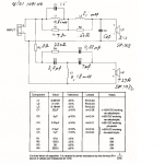
I use Jeff Bagby's Passive Crossover Designer (PCD v.7) for my simulation of the crossover design. Baffler diffraction was accounted for using the "Response Modeler" program. Both of these programs run in Excel.
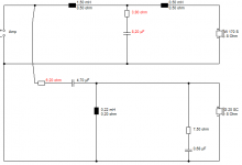
The crossover below has the stock Falcon HF and the LF is modified for the Peerless by simulation. I am looking for help to convert the HF section to acoustic Butterworth topology.

6" paper Peerless 830875 Nomex. A hopeless case, IMO.
The polycone 830874 looked better. It's not really the tweeter that is the problem.
More the horrible midrange shout of the woofer on a simple crossover.
Steve, thank you for the encouragement about the Nomex. LOL.
The upper midrange peak of the 830475 is typical of almost all plastic cone woofers and it is well established on how to tame it. What is your definition of a "simple crossover"? I will post the PCD simulation response results later.
Larry Hughes used the Sonaudax HD17B25H in the original design. What is a good substitute in your opinion?
When I did the search, I found many designs in US and Austratia used the Nomex. I like its cast aluminum frame, the plastic cone and reasonably strong magnet. It is priced right. I got 4 of them. I will probably go through my project with them for now. But I will appreciate any suggestion for improvement for the future.
Yes, the stock Falcon crossover with the Audax HS12x9D25 sound very good to me. It is NOT a problem per sec. I am just looking to try the benefit of a aB topology in the spirit of a DIYer.
Last edited:
Where does a 830475 come into it? I'm getting confused.
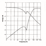
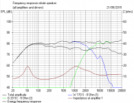
More detail revealed as the thread goes on...I would have liked to see that schematic in the first place. Impedance goes a bit low at 4kHz doesn't it?
That third order bass is a reasonable approach, IMO. Maybe a little 2.2R resistor in the 5uF shunt might give gentler rolloff?
Doesn't play very nicely on phase with the third order tweeter though by my rough simming. A second order (3.3uF) tweeter seems to work better and flatter with the resistor in front of the filter.
Troels Gravesen likes this sort of filter:
Studio-101
4.5kHz notch, 800Hz midrange notch and a Zobel on the tweeter. Just woolgathering really.
Last edited:
Where does a 830475 come into it? I'm getting confused.
More detail revealed as the thread goes on...I would have liked to see that schematic in the first place. Impedance goes a bit low at 4kHz doesn't it?
That third order bass is a reasonable approach, IMO. Maybe a little 2.2R resistor in the 5uF shunt might give gentler rolloff?
Doesn't play very nicely on phase with the third order tweeter though by my rough simming. A second order (3.3uF) tweeter seems to work better and flatter with the resistor in front of the filter.
Troels Gravesen likes this sort of filter:
Studio-101
4.5kHz notch, 800Hz midrange notch and a Zobel on the tweeter. Just woolgathering really.
The results of my simulation using the PCD. Schematics in my reply to AllenB.


The enclosure is a 15 litres closed box heavily braced.
This is my first attempt to use speaker simulation programs. Your critique is most welcome.
Interestingly, I was first steered to the Peerless HDS 830875 Nomex woofer by Troels Gravesen in his 2011 "Peerless Nomex 164" article.
PEERLESS-NOMEX-164
I was looking for a good quality 6.5" at affordable price. I set my goal as a cast frame and low distortion (Maximum Linear Excursion>5mm). When I found out I can get the 830875 or the 830874 for less than $60 a piece, I was sold on that.
I decided on the 830875 instead of the 830874 because of the work by Joe Rasmussen on the Elsinore Mk5.
Elsinore Nomex Drivers
Your experience and opinion on this drive is appreciated.
PEERLESS-NOMEX-164
I was looking for a good quality 6.5" at affordable price. I set my goal as a cast frame and low distortion (Maximum Linear Excursion>5mm). When I found out I can get the 830875 or the 830874 for less than $60 a piece, I was sold on that.
I decided on the 830875 instead of the 830874 because of the work by Joe Rasmussen on the Elsinore Mk5.
Elsinore Nomex Drivers
He emphasized that the difference is very subtle and the user should not hesitate to select whatever is available.I am leaning towards the Nomex is that they just seem to sound that touch bit more real
Your experience and opinion on this drive is appreciated.
Last edited:
I've talked with Joe. He has a lot to say about crossovers and is a fan of conjugating its load to the amp. What I like about the Elsinore is that builders have good words to say and collaborate in it's development. Perhaps the line array has something to do with its qualities as well.
Enjoying this thread, keilau. You are making me think!
Reason I hate 6 inch paper drivers in general, is I have a job getting them to sound good!
Below is a little 10L speaker I usually feel like kicking round the room. And I've done about 5 crossovers for it. It's quite detailed, but it's never tonally right!
Your third order filter looks really useful. I think you need some shunt resistance to get rid of the peak at crossover. And second order tweeter is indicated. It seems to work best on as narrow a baffle as you can get away with too.
I suspect the polycone is easier on phase above 5kHz. A lot of classic designs used 6" polycone. It's quite well behaved and has more rolloff. With a paper cone there is maybe something to be said for adding a 22R and 0.68uF tank notch to the 1.5mH bass coil, and upping the tweeter capacitor to 6.8uF to fill the hole. Phase is way better.
Most of what I have done with 6 inch bass says 2nd order bass doesn't work well. Even with a ca. 5kHz notch. A work in progress. I follow the elsinore with interest too.
For all that, we seem to be finding that a KEF AB is hardly relevant here. And 0.15uF will do next to nothing anyway. Oh, whoops, I used a 0.22mH coil. Well it might have more presence with 0.25mH anyway! Reference conjugating, this speaker has a very undemanding flattish impedance anyway. No amplifier should struggle.
Attachments
Last edited:
Steve, thank you again for your reply.
I am actually building 2 pairs of bookshelf speakers. The other is further along. It uses the same 830875 Nomex woofer and the Dayton Audio RS28A-4 aluminum dome tweeter. The tweeter is made by Usher Audio in Taiwan. I want to try something different from the solf dome that I had used a lot. I will probably stick with the drivers because of the investment in money and labor. But the critical crossover still has lots of room for improvement. Your critique is most welcome.
The bookshelfs will be used with aperiodic speakers with twin 7" woofers per side from Wharfedale as subwoofers.
- Status
- This old topic is closed. If you want to reopen this topic, contact a moderator using the "Report Post" button.
- Home
- Loudspeakers
- Multi-Way
- Converting 3rd order Butterworth to aB