Did you have something in mind or did you just select me at random for an insult?
Ben
I do not intent insult for sure, accept my apology if you are hurt!
I just want to confirm that you refuse to read the five lines after the first and then miraculously you interpret them with other words while arguing with my statement which is the same as yours, only that you refuse to admit reading it.
Thank you for reading!
And somulations-measurements-listening experience coincide, take my personal testimony on that! This is the reason we measured at 1.8 m (6ft), we were walking around the speakers. We also measured sitting height an off axis. It all was, you hear it, it is in the measurement.
You go to Mathcad or the Edge and mo e the microphone and the SPL curve is the same as heard or measured.
This applies to open and closed baffles. Diffraction based irregularities will only be 'fixed' for one listening point, making others worse. I wonder why I don't see more dipoles with rounded over edges to eliminate the issue?See the attached screenshot. With Irregular OB, you can completely eliminate the OB peak.
But the radiation pattern of the speaker becomes very irregular and also asymetric.
Last edited:
^A dipole baffle's rounded egdes don't mean a thing in the dipole operating range! Edge diffractions play a role only higher, above the dipole peak!
Varying distance from radiating center to edges distributes(messes) dipole peak/null just like edge diffractions.
Edge rounding means often widening of baffle, which means lowering of dipole peak and null.
In dipole models/simulations like Edge, the baffle has no depth, it is just a solid membrane (I suppose) Baffle thickness (or U/H shape) and rounding must be calculated in baffle's virtual width!
More info in German by Rudolf Finke http://www.dipolplus.de/thema4.html
Last edited:
So what you're saying is that the dipole operating range is the equivalent to the usual baffle step diffraction in it's region?
I think that diffraction is a bigger issue at higher frequencies. I happen to dislike allowing baffle step but it can be managed.. but higher frequency diffraction produces level dependent harshness and might be involved in speaker localisation.
Earl Geddes has suggested a way around this for dipoles.. a toroidal baffle. I'm surprised it hasn't caught on.
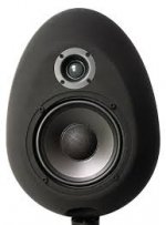
Here's an egg-shaped enclosure. I have 4 of these from 1978.Earl Geddes has suggested a way around this for dipoles.. a toroidal baffle. I'm surprised it hasn't caught on.
B.
Attachments
Last edited:
So what you're saying is that the dipole operating range is the equivalent to the usual baffle step diffraction in it's region?
Yep. This picture is from Rudolf, link in my previous post. Dipole operation up to 3kHz (notice constant directivity), then all kinds of diffractions and cone directivity issues above it. Notice also how dipole peak/null shifts with off-axis
Last edited:
This seems to be the thing with diffraction, peaks change in frequency with angle. This differentiates it from something that could be equalised. Where would you cross this example?Notice also how dipole peak/null shifts with off-axis
Earl Geddes has suggested a way around this for dipoles.. a toroidal baffle. I'm surprised it hasn't caught on.
A good idea, but not wihtout its pitfalls: with a toroidal baffle one is essentially also creating a (double) waveguide, its effect depending on the toroid radius, positioning, etc. and this has to be taken into account. I do reckon, however, that this can be used as an advantage for controlling directivity at HF, where dipole behavior ceases.
- Status
- This old topic is closed. If you want to reopen this topic, contact a moderator using the "Report Post" button.
- Home
- Loudspeakers
- Multi-Way
- Confused OB project