I've been using my Woofer Tester 2 (WT2) for many years to determine T/S paramaters for speaker drivers. The device uses very low voltage (mV) level during the test. However, the voltage level meter on the software does show a little over 1 V after calibration and before the leads are attached to the DUT. The WT web site states their device measures at constant current. I've noted that during a test as each successive datapoint in plotted, the current returns to about 3.6 mA when testing a woofer with a Re of 7.35 ohms.
It's come to my attention recently that some commercial driver manufacturers are now using voltages in the 1-3 volts range. https://www.madisoundspeakerstore.c...oofer-neo/ferrite-magnet-copper-sleeve-8-ohm/
The Morel T/S table shows a comparison of results on small signal vs 1 volt drive levels. This huge increase gives T/S values significantly different from the classic low voltage ones we've been using for years in our speaker designs. To me, this is a disturbing development that alters our assumptions used in modeling. How is this accounted for????
Are any of you DIY'rs using higher voltage level in your testing? What device are you using?
Last edited:
I've been using my Woofer Tester 2 (WT2) for many years to determine T/S paramaters for speaker drivers. The device uses very low voltage (mV) level during the test. However, the voltage level meter on the software does show a little over 1 V after calibration and before the leads are attached to the DUT. The WT web site states their device measures at constant current. I've noted that during a test as each successive datapoint in plotted, the current returns to about 3.6 mA when testing a woofer with a Re of 7.35 ohms.
It's come to my attention recently that some commercial driver manufacturers are now using voltages in the 1-3 volts range. https://www.madisoundspeakerstore.c...oofer-neo/ferrite-magnet-copper-sleeve-8-ohm/
The Morel T/S table shows a comparison of results on small signal vs 1 volt drive levels. This huge increase gives T/S values significantly different from the classic low voltage ones we've been using for years in our speaker designs. To me, this is a disturbing development that alters our assumptions used in modeling. How is this accounted for????
Are any of you DIY'rs using higher voltage level in your testing? What device are you using?
I've used LAUD, Praxis, SoundEasy and REW over the years. Depending on the application I will test using the constant voltage (relatively low value series current sense resistor) method at a variety of different voltages, and model the enclosure with all of the results.
In many cases the parameter shifts effectively cancel each other yielding a response that isn't that far off as the parameters shift.
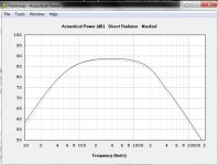
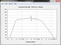
I modeled the Morel in HornResp, sealed and vented, 14L each time. Dark line is the small signal parameters, grey line the 1V parameters. In a room I think you'd be hard pressed to find a difference between them. In fact, I bet you'd see more variance in driver production runs. With the high dollar Morel, Scan-Speak, Seas and other well regarded speakers the variance will be small between runs and within runs.
Lesser brands....eh...the buyer should definitely measure every driver.
Attachments
Are any of you DIY'rs using higher voltage level in your testing? What device are you using?
I use LMS and DATS. With LMS, I can set the voltage whereas DATS is fixed.
The main advantage with LMS is it plots 2 graphs, one in free air and the other either with mass or volume. The two plots must look the same for the measurements to be accurate. Only the Fs is shifted.
DATS is much faster but only one plot. No comparison possible.
Regards
Mike
Attachments
I was reading up about DATS yesterday at the Parts Express website and recall it saying voltage was adjustable. Here's a quote from the DATS white paper downloadable at the PE site DATS page
"DATS allows the user to set the level of the test signal sweep anywhere in the range from +5 dBu (2 volts peak) to -10 dBu (0.35 V peak) within the software."
PE is now selling a ver. 2 which may be different from yours.
I also did some reading up on my WT2 and found it measures at constant current. I also have a WTPro which allows interface with an amp that I can then use to adjust driving voltage. Haven't tried it yet but will report results when I do.
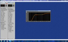
Here's my modeling of a SS 18W/4531G00 woofer based on SS spec sheet and my WT2 tests. It appears the final outcome in a 1.25 cu. ft. vented box is essentiall the same - much to my surprise. Red plot is SS specs model and yellow the Wt2 data model.
As I said before it's been my experience that the parameter shifts effectively cancel each other. Sure there's small differences...but not major. At least one pro manufacturer quotes xMax as a function of parameters, the parameters don't shift that much over that excursion range.
I have seen larger response shifts with small shifts in T/S type parameters when you start looking at higher compression horn loaded designs such as tapped horns or offset driver conical horns...but not typically with sealed or vented designs.
This is an important question small signal vs large signal models.
some things just can't be cancelled out like Le and Re, they can be averaged.
OEMs have done some improvements on high end motors so the delta should be so great, but lots have not.
Indeed speakers change their sonic character according to the volume but our ears adapt too.
some things just can't be cancelled out like Le and Re, they can be averaged.
OEMs have done some improvements on high end motors so the delta should be so great, but lots have not.
Indeed speakers change their sonic character according to the volume but our ears adapt too.
This is an important question small signal vs large signal models.
some things just can't be cancelled out like Le and Re, they can be averaged.
OEMs have done some improvements on high end motors so the delta should be so great, but lots have not.
Indeed speakers change their sonic character according to the volume but our ears adapt too.
Forr's post #2 has an interesting read on the subject at the link provided.
Initially, I thought the wide disparity in T/S results at low and elevated voltages would yield much larger differences in the model. However, it seems that is not the case.
Last edited:
At least one pro manufacturer quotes xMax as a function of parameters, the parameters don't shift that much over that excursion range.
Ive seen huge shifts in Le according to displacement, esp in high Le subs.
what does your data say? pole shrting rings can help but some are better than others
Re vs higher power / temp coeff. of copper and alum is significant.
Forr's post #2 has an interesting read on the subject at the link provided.
would yield much larger differences in the model. However, it seems that is not the case.
yeah he touches on the issue, but other than that it's a marketing white paper.
ie buy mine.
please share your data, rather than dismissing it.
Last edited:
- Status
- This old topic is closed. If you want to reopen this topic, contact a moderator using the "Report Post" button.
- Home
- Loudspeakers
- Multi-Way
- Woofer testing voltage level question