
A waveguide!
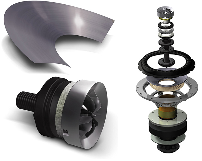
Of course it's a waveguide! Inspired by Dave Pellegrenes impressive results I threw a simple CAD together and made a small print. This is a 100x80x40 mm waveguide (~4 x 3 x 2") with a 1/2" throat. Lucky for me it was a test, it was supposed to be a 1" throat
Here it is straight from the printer:


It took 2 hours to print and weighs 55 g, material cost about 2 USD.
Removal of support material took about 1 min:

The purpose of the support material is to prevent sag around the screw holes.
Here is a close up:

This is the kind of surface you can expect directly from the printer. Add som primer and matte paint and I'm guessing the finish is acceptable for most.
All I've heard when people start talking about 3D-printing speaker parts is that it's too expensive, that the surface finish is crap and that it's somehow difficult. This was none of those things. The 3D-printer costs 900 USD (Wanhao Duplicator 4S) and the material 30 USD for 1 kg. The CAD took 1 hour to make (parametric geometry and new software), next one with other dimensions takes 2 minutes.
The only part I could possibly break of with my hands is the flange with mounting holes (waveguide->baffle). It has 1.2 mm thick walls and 30 % infill (as visible in the first post).
Of course it's a waveguide! Inspired by Dave Pellegrenes impressive results I threw a simple CAD together and made a small print. This is a 100x80x40 mm waveguide (~4 x 3 x 2") with a 1/2" throat. Lucky for me it was a test, it was supposed to be a 1" throat
Here it is straight from the printer:
It took 2 hours to print and weighs 55 g, material cost about 2 USD.
Removal of support material took about 1 min:
The purpose of the support material is to prevent sag around the screw holes.
Here is a close up:
This is the kind of surface you can expect directly from the printer. Add som primer and matte paint and I'm guessing the finish is acceptable for most.
All I've heard when people start talking about 3D-printing speaker parts is that it's too expensive, that the surface finish is crap and that it's somehow difficult. This was none of those things. The 3D-printer costs 900 USD (Wanhao Duplicator 4S) and the material 30 USD for 1 kg. The CAD took 1 hour to make (parametric geometry and new software), next one with other dimensions takes 2 minutes.
The only part I could possibly break of with my hands is the flange with mounting holes (waveguide->baffle). It has 1.2 mm thick walls and 30 % infill (as visible in the first post).
Thanks! I'm using Simplify3D as well, tried free options but they were horribly slow. I have not seen the SEOS profile as *.stl. I made a circular OS profile, that was easy. But the elliptical is slightly more difficult.Nice work! I am at about te same point as you - the software is key to make it easy. I got the Simplify3d suite which integrates all software functions needed after one has the STL file.
Is there an STL file of a horn in the SEOS thread?
/Anton
This is a comparison of the 100x80x40 mm waveguide I printed yesterday and close to the biggest that will fit in our printer:

That's 210x140x80 mm (maximum is 225x145x150 mm). I added a roundover at the mouth, not sure i should (more difficult to print, Pellegrene guides have very little roundover). Printing time is about 7 h.
Maybe the most interesting thing about 3D-printing waveguides is the possibility to incorporate phase-plugs with almost any shape. Here I need some help...
My plan is to use either the D2604/833000 after seing Dave Pellegrenes results here. Before we had the 3D-printer I was planning on buying from him, I still might if I can't get good results myself. I'm hoping I can make a deeper waveguide and thereby increase directivity, and maybe incorporate a phase-plug.
Three questions:
1. What profile should I use? Right now it's a simple conical waveguide. When looking at the Pellegrene waveguides there seems to be some kind of change in slope close to the throat. OS?
2. What mouth shape should I use. When looking at the Pellegrene guides I think the elliptical guides have best behavior in the top octave. But a rounded rectangular mouth is also possible:

3. How do I design a phase-plug? Where do I start? My understanding is that the purpose of it is to make the pathlengths (more) equal. So the simplest one should be a small lump (sphere, ellipsoid?) close to the center of the dome to increase the pathlength for waves eminating from the top, correct?
/Anton
That's 210x140x80 mm (maximum is 225x145x150 mm). I added a roundover at the mouth, not sure i should (more difficult to print, Pellegrene guides have very little roundover). Printing time is about 7 h.
Maybe the most interesting thing about 3D-printing waveguides is the possibility to incorporate phase-plugs with almost any shape. Here I need some help...
My plan is to use either the D2604/833000 after seing Dave Pellegrenes results here. Before we had the 3D-printer I was planning on buying from him, I still might if I can't get good results myself. I'm hoping I can make a deeper waveguide and thereby increase directivity, and maybe incorporate a phase-plug.
Three questions:
1. What profile should I use? Right now it's a simple conical waveguide. When looking at the Pellegrene waveguides there seems to be some kind of change in slope close to the throat. OS?
2. What mouth shape should I use. When looking at the Pellegrene guides I think the elliptical guides have best behavior in the top octave. But a rounded rectangular mouth is also possible:
3. How do I design a phase-plug? Where do I start? My understanding is that the purpose of it is to make the pathlengths (more) equal. So the simplest one should be a small lump (sphere, ellipsoid?) close to the center of the dome to increase the pathlength for waves eminating from the top, correct?
/Anton
1. What profile should I use? Right now it's a simple conical waveguide. When looking at the Pellegrene waveguides there seems to be some kind of change in slope close to the throat. OS?
The profile that is best suited to the shape of your tweeter dome and surround. Simulating the propagation of the sound in 3D should help you determine this.
2. What mouth shape should I use. When looking at the Pellegrene guides I think the elliptical guides have best behavior in the top octave. But a rounded rectangular mouth is also possible:
The shape that provides the directivity that the speaker requires to match the other drivers and the room it will be used in. This is very unlikely to be a round waveguide but it is also likely to change from speaker to speaker.
3. How do I design a phase-plug? Where do I start? My understanding is that the purpose of it is to make the pathlengths (more) equal. So the simplest one should be a small lump (sphere, ellipsoid?) close to the center of the dome to increase the pathlength for waves eminating from the top, correct?
Assuming a standard dome tweeter then the KEF phase plugs they use on their coaxial tweeters is likely to be a reasonable starting point.
It is an interesting project you have set yourself but it strikes me that you probably need to learn a bit more about the physics of what is going on before you can create a successful design of your own. An alternative might be to team up with someone with knowledge in the area and work on a joint design.
You are completely correct in your last part, I don't know enough to do this by myself. That's why I'm here! I'm not in a hurry, I want to learn and I think other people in this community could be interested/benefit from this. 3D-printers are getting cheap and increasingly common at work places.The profile that is best suited to the shape of your tweeter dome and surround. Simulating the propagation of the sound in 3D should help you determine this.
The shape that provides the directivity that the speaker requires to match the other drivers and the room it will be used in. This is very unlikely to be a round waveguide but it is also likely to change from speaker to speaker.
Assuming a standard dome tweeter then the KEF phase plugs they use on their coaxial tweeters is likely to be a reasonable starting point.
It is an interesting project you have set yourself but it strikes me that you probably need to learn a bit more about the physics of what is going on before you can create a successful design of your own. An alternative might be to team up with someone with knowledge in the area and work on a joint design.
Is it something like this I should try?
I've started doing some simulations in COMSOL Multiphysics to look at how the waveguide shape affects the directivity. I'll post some pics later so we can discuss whether the model is reasonable or not.
A little background
My living room looks like this:


The media console contains one subwoofer at each end and all the electronics in the middle.
My plan is to build a speaker that looks like this:

or this:

I don't have any drivers yet, but the plan is to match the directivity of the waveguide by rear mounting the midbass and chamfer the (thick) baffle, like seen in the last pic. As my chamfer bit is 45 degrees I'm starting with that, i.e. a horisontal directivity of about 90 degrees, I'm guessing a little higher due to the shallow "waveguide" that the chamfering will make. Vertical directivity should be narrower and I'll need to do that by careful selection of ctc distance and crossover.
/Anton
Is it something like this I should try?
Perhaps. My only experience with cheap "3d printers" was in the mid 90s when they were called desktop rapid prototype machines. We were offered one for free by the manufacturing department if our department took over the maintenance contract. A bit of investigation determined that both the surface finish and the sagging made it unsuitable for the small aerodynamic parts we wanted to make which looked quite a lot like that KEF phase plug in size and shape except the blades were at an angle to the air. We stayed with the remote and expensive rapid prototype machine that we had been using.
I've started doing some simulations in COMSOL Multiphysics to look at how the waveguide shape affects the directivity. I'll post some pics later so we can discuss whether the model is reasonable or not.
That looks like good software to get the answers subject to asking the right questions (and having the appropriate modules and access to a big enough computer). I look forward to seeing some of the results from the simulations.
My plan is to build a speaker that looks like this:
Close to a wall like that will cause significant issues with the strong reflection off the back wall causing cancellation and reinforcement with the direct sound. It may be wise to consider a speaker designed to work flat against a wall and, optionally, placed on a surface. A waveguide on the tweeter directing the high frequencies is not going to help unfortunately because the most problematic frequencies tend to be at a few hundred Hz.
I think a lot has happened in the last 20 years when it comes to 3D-printers. I have the possibility to print supportmaterial in water soluble PVA which suposedly increases print quality considerably for difficult geometries. The nozzle is 0.4 mm in diameter which sets some kind of smallest dimension when it comes to size.Perhaps. My only experience with cheap "3d printers" was in the mid 90s when they were called desktop rapid prototype machines. We were offered one for free by the manufacturing department if our department took over the maintenance contract. A bit of investigation determined that both the surface finish and the sagging made it unsuitable for the small aerodynamic parts we wanted to make which looked quite a lot like that KEF phase plug in size and shape except the blades were at an angle to the air. We stayed with the remote and expensive rapid prototype machine that we had been using.
That looks like good software to get the answers subject to asking the right questions (and having the appropriate modules and access to a big enough computer). I look forward to seeing some of the results from the simulations.
Close to a wall like that will cause significant issues with the strong reflection off the back wall causing cancellation and reinforcement with the direct sound. It may be wise to consider a speaker designed to work flat against a wall and, optionally, placed on a surface. A waveguide on the tweeter directing the high frequencies is not going to help unfortunately because the most problematic frequencies tend to be at a few hundred Hz.
I used my lunch break to go to my local speaker shop to buy a D2604/8330000, they sold the last one yesterday :/ They did however have a R2604/8330000, so I bought one for testing. It seems to be the same as the XT25BG60, which is the same as the XT25TG30 with an additional magnet (and larger back chamber). The latter one behaves like this in an 8x5 waveguide:
This is the D2604/8330000 in the same waveguide:

Quite similar, except the XT25TG30 looses some output above ~12 kHz. Probably fixable in my nanoAVR.
The proximity to the wall is indeed a problem, I'm hoping it is (partly) solvable by adding a damping panel behind the speakers, maybe something like this:

(Ignore the speaker, old rendering)
I can't move the speaker further than a feet from the wall due to how the room looks.
/Anton
I think a lot has happened in the last 20 years when it comes to 3D-printers.
Perhaps but the same basic problem of surface finish and sag remain. It will be interesting to see by how much they have improved.
Probably fixable in my nanoAVR.
My guess would be throat geometry. Your Comsol simulations should hopefully tell you a lot about this sort of thing. You are aware of the Comsol studies by Harman on waveguides like this. I think there are more publications on the subject if you dig around.
Absorption will not work. At low frequencies in order to be effective you will need absorption that is as deep as the distance from the speaker baffle to the rear wall. Even then you do not want normal room absorption but to almost completely remove the rear wave. I think more realistic options might be to ignore it or design a speaker to work flat against the wall.The proximity to the wall is indeed a problem, I'm hoping it is (partly) solvable by adding a damping panel behind the speakers, maybe something like this:
(Ignore the speaker, old rendering)
I can't move the speaker further than a feet from the wall due to how the room looks.
There are a bunch of long threads on the shape of these waveguides. I think the simplest may be the oblate spheroid which resembles a round cone with a short straight secrion to the throat of the CD with a round over transition from the short cylinder to the cone and one more round over at the rim. This looks like the Geddes waveguide. There is the more conplicated super elliptical oblate spheroid (SEOS) and there is a long thread on that with all the math.
But one can just buy a 12 in SEOS for about $15 to $30. It may cost you almost that much in filament alone and you are limited to 8in max width and height typically.
But one can just buy a 12 in SEOS for about $15 to $30. It may cost you almost that much in filament alone and you are limited to 8in max width and height typically.
Last edited:
Alright, I'll start with the OS/SEOS approach. Have they been used for domes/ringradiators? I downloaded the OS-spreadsheet and made two curves, one for 45 degree and one for 55 degrees (both with 10 degree throat angle). Put those into Creo (CAD software) together with a circle at one end and an ellipse in the other. Used Boundary Blend to create a surface and ended up with this:There are a bunch of long threads on the shape of these waveguides. I think the simplest may be the oblate spheroid which resembles a round cone with a short straight secrion to the throat of the CD with a round over transition from the short cylinder to the cone and one more round over at the rim. This looks like the Geddes waveguide. There is the more conplicated super elliptical oblate spheroid (SEOS) and there is a long thread on that with all the math.
But one can just buy a 12 in SEOS for about $15 to $30. It may cost you almost that much in filament alone and you are limited to 8in max width and height typically.

looks reasonable, just the rounding missing. Is this the correct approach? Is it supposed to be a super-ellipse?
Converted to solid with a 1/2" roundover:

Time for some simulations!
/Anton
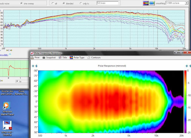
First sims!
All simulations assume a fix acceleration of the voice coil, no roll-off. Mic is always 1 m from diaphragm. Waveguide is fitted around the surround (not over), circular hole is 38 mm diameter.
First a simulation of the R2604 in a flat baffle:

Measurement from Scan-Speak:

Quite similar, linear increase in directivity followed by large dips off axis.
I started with the simplest axisymmetrical conical round waveguides. Here follows 3 figures where only the depth is varied between 30, 60 and 90 mm. All guides have a diameter of 200 mm (8").


Deeper = better directivity and higher off axis dip but more ragged response.
Here is the 60 mm deep guide with 1/2" rounding and 2" rounding:


1/2" does seemingly nothing, 2" is however a considerable improvement.
This is how the geometry looks:

Grey is simulated volume (tweeter is firing down in pics), blue is the parts that are moving on the tweeter. The ringradiator design is a bit special as it is basically only two surrounds and no dome/diaphragm. I chose to simulate the movement like this:

A specified acceleration where the two surrounds are attached to the voice coil and linearly decreasing to 0 where they are attached to the frame.
For those not familiar with FEM: The geometry is divided into many very small parts, it's called meshing. This is what the mesh looks like:

It needs to be very dense if we want to see what happens at 20 kHz.
This is what the pressure field looks like for the 200x60 (1/2" rounding) waveguide at ~3 kHz:

And at 10 kHz:

Next: Simulating an OS-waveguide.
/Anton
All simulations assume a fix acceleration of the voice coil, no roll-off. Mic is always 1 m from diaphragm. Waveguide is fitted around the surround (not over), circular hole is 38 mm diameter.
First a simulation of the R2604 in a flat baffle:
Measurement from Scan-Speak:
Quite similar, linear increase in directivity followed by large dips off axis.
I started with the simplest axisymmetrical conical round waveguides. Here follows 3 figures where only the depth is varied between 30, 60 and 90 mm. All guides have a diameter of 200 mm (8").
Deeper = better directivity and higher off axis dip but more ragged response.
Here is the 60 mm deep guide with 1/2" rounding and 2" rounding:
1/2" does seemingly nothing, 2" is however a considerable improvement.
This is how the geometry looks:
Grey is simulated volume (tweeter is firing down in pics), blue is the parts that are moving on the tweeter. The ringradiator design is a bit special as it is basically only two surrounds and no dome/diaphragm. I chose to simulate the movement like this:
A specified acceleration where the two surrounds are attached to the voice coil and linearly decreasing to 0 where they are attached to the frame.
For those not familiar with FEM: The geometry is divided into many very small parts, it's called meshing. This is what the mesh looks like:
It needs to be very dense if we want to see what happens at 20 kHz.
This is what the pressure field looks like for the 200x60 (1/2" rounding) waveguide at ~3 kHz:
And at 10 kHz:
Next: Simulating an OS-waveguide.
/Anton

Great work Onni. Are you using ABEC3 or is this Comsol Multiphysics?
You know, when I see FEM/FEA (BEM) analysis done I sometimes cringe at the expense of the modeling.
(..yes, ABEC3 is available for "free" as a DIY, but it's not terribly user friendly and its commercial pricing is still very pricey.. if not in the league of Comsol. ..and commercial "add-on's" to various CAD programs often cost more than a grand, sometimes a lot more.)
Here is why I "cringe":
Ex.: https://www.csc.fi/web/elmer
Ex.: Welcome to the www.salome-platform.org — SALOME Platform
Last edited:
Thanks! This is using Comsol, I tried looking at ABEC3 (I have a student license), I'm not comfortable using it yet though.Great work Onni. Are you using ABEC3 or is this Comsol Multiphysics? Can you show more details on the math behind the SEOS? That profile looks very nice. Looking forward to a STL file for one with a 3/2 bolt flange CD with 1in dia throat
The math is pretty simple. I'll post the method. If there is interest I could make *.stl files for people to test 😊
/Anton
It is good to see simulations like this because it reveals and quantifies what is important in the physics and what is less so in a way that is rarely seen in most discussions on this forum.
The roll-off is easy enough to include. What you can see at higher frequencies is that the motion of the membrane is not following the assumed motion but that some resonant/wave motion is starting to play a role. I would suggest putting the measurements and your simulations on the same plot because it is likely to be helpful with the interpretation of the waveguide plots.
A good illustration of why a spherical waveguide is unlikely to be a good idea. Of course sitting off axis avoids the worst of the raggedness.
I would suggest repeat runs with the exit moved both closer and further away using the deepest waveguide. I would include both the location of the boundary condition and the location of the strong change in grid resolution which may also be changing the effective impedance. Locating the exit boundary far enough away to have only a small influence on what you are interested in often needs to be determined in this manner.
2" is large compared to the dimensions of a typical tweeter waveguide. You have yet to study changes to the throat to improve the response which is going to leave little room for whatever profile takes your fancy.
Most commercial waveguides look fairly flat to me but what you probably want to seek to achieve is that the wavefront is as close to 90 degrees to the guide as possible in order that the reflected wave is minimised. This is where your throat shape and phase plug come in because at higher frequencies the wavefront at the throat is likely to be a long way from ideal. A sharp edge to cause strong diffraction may even help overall in getting the wavefront into the right shape and moving in the right direction down the guide.
There is no need to achieve perfection in simulations so long as you understand the sources of error and can back them out to the extent they do not significantly distort what you are studying. A good example of this is the low frequency roll-off above.
Highly accurate discretizations like spectral methods can approach 2 elements per wavelength. High order FEM elements might need 4-8 elements per wavelength with low order methods needing 10-20 elements per wavelength.
Sound waves are smooth and so the most efficient combination is to use low density meshes with a high order elements (subject to using enough elements).
To check if your combination of grid density and discretization scheme is sufficient you should perform a simulation with twice the density of elements and half the density of elements and compare the results. You want to be using enough elements to be approaching grid independence where increasing the grid density doesn't change the answer.
Good stuff. I look forward to seeing lots more.
All simulations assume a fix acceleration of the voice coil, no roll-off. Mic is always 1 m from diaphragm. Waveguide is fitted around the surround (not over), circular hole is 38 mm diameter.
First a simulation of the R2604 in a flat baffle:
Measurement from Scan-Speak:
Quite similar, linear increase in directivity followed by large dips off axis.
The roll-off is easy enough to include. What you can see at higher frequencies is that the motion of the membrane is not following the assumed motion but that some resonant/wave motion is starting to play a role. I would suggest putting the measurements and your simulations on the same plot because it is likely to be helpful with the interpretation of the waveguide plots.
I started with the simplest axisymmetrical conical round waveguides. Here follows 3 figures where only the depth is varied between 30, 60 and 90 mm. All guides have a diameter of 200 mm (8").
Deeper = better directivity and higher off axis dip but more ragged response.
A good illustration of why a spherical waveguide is unlikely to be a good idea. Of course sitting off axis avoids the worst of the raggedness.
I would suggest repeat runs with the exit moved both closer and further away using the deepest waveguide. I would include both the location of the boundary condition and the location of the strong change in grid resolution which may also be changing the effective impedance. Locating the exit boundary far enough away to have only a small influence on what you are interested in often needs to be determined in this manner.
Here is the 60 mm deep guide with 1/2" rounding and 2" rounding:
1/2" does seemingly nothing, 2" is however a considerable improvement.
2" is large compared to the dimensions of a typical tweeter waveguide. You have yet to study changes to the throat to improve the response which is going to leave little room for whatever profile takes your fancy.
Most commercial waveguides look fairly flat to me but what you probably want to seek to achieve is that the wavefront is as close to 90 degrees to the guide as possible in order that the reflected wave is minimised. This is where your throat shape and phase plug come in because at higher frequencies the wavefront at the throat is likely to be a long way from ideal. A sharp edge to cause strong diffraction may even help overall in getting the wavefront into the right shape and moving in the right direction down the guide.
This looks like the best starting point although, as mentioned above, the measured response on a flat baffle suggests a noticeable deviation from this at higher frequencies. It is likely to take a significant effort to improve this boundary condition which may or may not be cost effective depending on where things go later.This is how the geometry looks:
Grey is simulated volume (tweeter is firing down in pics), blue is the parts that are moving on the tweeter. The ringradiator design is a bit special as it is basically only two surrounds and no dome/diaphragm. I chose to simulate the movement like this:
A specified acceleration where the two surrounds are attached to the voice coil and linearly decreasing to 0 where they are attached to the frame.
There is no need to achieve perfection in simulations so long as you understand the sources of error and can back them out to the extent they do not significantly distort what you are studying. A good example of this is the low frequency roll-off above.
Sound waves at constant frequency have a constant wavelength. The numerical error associated with a particular grid size will distort the shape of a weak wave near the exit by the same amount as a strong wave near the throat. This means the grid size should normally be uniform throughout the solution domain and is usually quoted in the form of number of elements per highest wavelength.For those not familiar with FEM: The geometry is divided into many very small parts, it's called meshing. This is what the mesh looks like:
It needs to be very dense if we want to see what happens at 20 kHz.
Highly accurate discretizations like spectral methods can approach 2 elements per wavelength. High order FEM elements might need 4-8 elements per wavelength with low order methods needing 10-20 elements per wavelength.
Sound waves are smooth and so the most efficient combination is to use low density meshes with a high order elements (subject to using enough elements).
To check if your combination of grid density and discretization scheme is sufficient you should perform a simulation with twice the density of elements and half the density of elements and compare the results. You want to be using enough elements to be approaching grid independence where increasing the grid density doesn't change the answer.
Good stuff. I look forward to seeing lots more.
You know, when I see FEM/FEA (BEM) analysis done I sometimes cringe at the expense of the modeling.
You clearly have not worked in an industrial environment where engineers use computer simulations everyday to evolve the design of products. The software is reducing the time the engineers spend designing and improving the quality of the design decisions by quantifying the processes involved. It also reduces the number of experimental tests that need to be performed. An engineer's time and experimental measurements are expensive compared to the price of commercial simulation software.
Here is why I "cringe":
Ex.: https://www.csc.fi/web/elmer
Ex.: Welcome to the www.salome-platform.org — SALOME Platform
My suspicion is that you haven't used the above in anger.
About 10 years ago I looked at using the Elmer software for a basic 3d Helmholtz solver. The first case I ran was a basic symmetry test and it failed with what looked inconsistent handling of edge boundary conditions. I got no response from CSC when I posted the failed test case. Reading the forum I suspected one of the CSC people had broken the code when fixing something earlier but this was a guess and perhaps it never worked properly in the first place. Now it is open source software and I could have fixed it myself as part of learning how to use it. But the absence of basic quality control in the form of tests, the lack of interest in the acoustic modules some of which have subsequently disappeared from in the documentation, the lack of response from CSC, etc... lead to me to conclude it was probably not a project worth a significant investment of time.
The Code-Aster software is a reasonable engineering package for those that are familiar with such packages and speak French. There is some basic user level English documentation but if you want to use it seriously then you need to look to the native documentation and code which is in French. If the acoustic support was stronger I probably would have stuck with it but it became clear I needed to add a fair amount and that would be very frustrating given that my school boy French was proving to be beyond rusty.
When it comes to large commercial engineering packages the cost is more for the support than the software itself.
- Home
- Loudspeakers
- Multi-Way
- 3D-printing