I did a small experiment today with the brown waveguide I printed during summer: measured the response after applying PEQ and LT.
All measured on axis at about 30 cm distance (I was mainly interested in phase behaviour). 1/12th octave smoothing, no gating.
RAW:

Impulse response RAW:

Distortion RAW:

Then I added 2 PEQs to flatten the response:

Impulse response:

Quite decent, but what if I add a Linkwitz-transform to counteract the rising phase towards lower frequencies?
Added LT has parameters f0 = 1300 Hz, Q0 = 0.6, fp = 600, Qp = 0.7. Result:

With 2 PEQs:

Impulse response:

Not bad at all! That should be easy to design a crossover for.
The LT increases the distortion at the low end (as expected):

But the intended crossover frequency is about 1500 Hz and when a Bessel HP is added (for a Harsch XO) it looks like this:

I haven't seen the use of LT on tweeters to flatten phase and thought I had a novel idea, but I did a search and it is of course mentioned by Linkwitz himself on his site") But if it's new to others I recommend testing it for easy crossover tinkering.
But if it's new to others I recommend testing it for easy crossover tinkering.
/Anton
All measured on axis at about 30 cm distance (I was mainly interested in phase behaviour). 1/12th octave smoothing, no gating.
RAW:
Impulse response RAW:
Distortion RAW:
Then I added 2 PEQs to flatten the response:
Impulse response:
Quite decent, but what if I add a Linkwitz-transform to counteract the rising phase towards lower frequencies?
Added LT has parameters f0 = 1300 Hz, Q0 = 0.6, fp = 600, Qp = 0.7. Result:
With 2 PEQs:
Impulse response:
Not bad at all! That should be easy to design a crossover for.
The LT increases the distortion at the low end (as expected):
But the intended crossover frequency is about 1500 Hz and when a Bessel HP is added (for a Harsch XO) it looks like this:
I haven't seen the use of LT on tweeters to flatten phase and thought I had a novel idea, but I did a search and it is of course mentioned by Linkwitz himself on his site
But if it's new to others I recommend testing it for easy crossover tinkering./Anton
Nice work Onni.
Your plot of the HD looks a lot like my plot of a bare ND25FA-4 tweeter from Dayton (here with 24dB/oct BW HPF, no EQ):
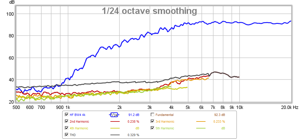
I am making a 3-way Harsch so the mid driver will be Bessel 2nd order on HPF and LPF and the woofer is BW4 and tweeter is BW4.
This $17 tweeter has some remarkable performance though. Of course doesn't have the directionality of your WG.
Your plot of the HD looks a lot like my plot of a bare ND25FA-4 tweeter from Dayton (here with 24dB/oct BW HPF, no EQ):
I am making a 3-way Harsch so the mid driver will be Bessel 2nd order on HPF and LPF and the woofer is BW4 and tweeter is BW4.
This $17 tweeter has some remarkable performance though. Of course doesn't have the directionality of your WG.
This $17 tweeter has some remarkable performance though. Of course doesn't have the directionality of your WG.
Dayton recently released that tweeter combined with a small waveguide...for about the same price as without the waveguide:
Dayton Audio ND25FW-4 1" Soft Dome Neodymium Tweeter with Waveguide 4 Ohm
Dayton recently released that tweeter combined with a small waveguide...for about the same price as without the waveguide:
Dayton Audio ND25FW-4 1" Soft Dome Neodymium Tweeter with Waveguide 4 Ohm
Thanks for the tip. I should have bought these instead.
Waveguide for 3" fullrange driver, possible ?
Hello,
I have a very small loudspeaker enclosure using Monacor SPH-30X-4.
Right now, as a test, I have a conical waveguide in front of it.
I used a Ikea bowl
I would like to 3D print a dedicated waveguide.
But, I have no clue of how to start
Someone may be interrested in helping ?
Thank you,
Jean
Hello,
I have a very small loudspeaker enclosure using Monacor SPH-30X-4.
Right now, as a test, I have a conical waveguide in front of it.
I used a Ikea bowl
An externally hosted image should be here but it was not working when we last tested it.
I would like to 3D print a dedicated waveguide.
But, I have no clue of how to start
Someone may be interrested in helping ?
Thank you,
Jean
I've been using CADCAM software for 28 years and though I don't have a lot of experience with Additive Manufacturing (3D printing) I can tell you that most popular CAD software has the ability to export the CAD model to an *STL file format.
I personally use Siemens NX (formally known as Unigraphics) which is a sophisticated 3D parametric modeler which also has manufacturing, analysis, inspection and other mechanical engineering tools. However there are others such as AutoCAD LT which is much less expensive but probably more than capable of doing the things most would need.
I personally use Siemens NX (formally known as Unigraphics) which is a sophisticated 3D parametric modeler which also has manufacturing, analysis, inspection and other mechanical engineering tools. However there are others such as AutoCAD LT which is much less expensive but probably more than capable of doing the things most would need.
I personally use Siemens NX (formally known as Unigraphics) which is a sophisticated 3D parametric modeler which also has manufacturing, analysis, inspection and other mechanical engineering tools.
You must work for someone with deep pockets.
jeff
You must work for someone with deep pockets.
jeff
I currently work for the largest machine tool builder and we have a partnership with Siemens because 75% of our machines come equipped with Siemens controllers. We get to use the CADCAM software for developing CNC programs for turnkey solutions.
Prior to that I worked for the largest jet engine company and before that I worked for the largest aircraft company.
Last edited:
Thanks! The main advantage of using a ringradiator IMO is that it fits inside the horn throat, no adapter is needed. The R2604 has an 1" VC, but an outer diameter of 38 mm, it starts beaming slightly above 10 kHz. A 3/4" VC ringradiator would start beaming at a higher frequency.Hey onni, nice work on the waveguide builds and COMSOL simulations! I've been wanting to utilise FEA in speaker design so this maybe a good starting point. Would you or anyone else see any problems moving down to a 3/4" entry for a 3/4" ring radiator?
/Anton
A 3/4" VC ringradiator would start beaming at a higher frequency. /Anton
Yes, that is one of the attractive features of the smaller diaphragm for me. The wider dispersion should allow the waveguide to have more pattern control at higher frequencies. Re: your chosen CAD software, I will be attending a free CREO training workshop the next couple of days. Will be good to see how it compares to Solidworks.
What softwares are you using, besides SketchUp, SolidWorks ?
Interesting (Dr. Roger Leir) in 5 years science will be able to reproduce a cardiac cell with compatible DNA in a 3D biological printer, on video 1:20:47/1:24:21
https://www.youtube.com/watch?v=wifuvvUKbf0
Interesting (Dr. Roger Leir) in 5 years science will be able to reproduce a cardiac cell with compatible DNA in a 3D biological printer, on video 1:20:47/1:24:21
https://www.youtube.com/watch?v=wifuvvUKbf0
Re: your chosen CAD software, I will be attending a free CREO training workshop the next couple of days. Will be good to see how it compares to Solidworks.
The numbers corresponding with the colored areas along the z-axis towards the mouth seem to indicate the radii at these specific points. Just my uneducated guess.I don't mistrust SolidWorks, but it has to do some assumptions on how the surface looks like between the six guide lines. I'll post some pics of what I mean from Creo when I get back to that computer (monday). What seems to happen is that for a superellipse that is closer to a rectangle than an ordinary ellipse it stretches the entire curve slightly. This causes the throat angle to be exact at the guide lines, but slightly too large between them. I also did the test with the waveguide I printed which is round and has n=1:

I used Inspect -> Slope, but I'm not sure what the numbers are saying. (If someone has experience with Creo/ProE, please explain!)
Please post some similar evaluations!
/Anton
Unnecessary post, because here is the solution (by Anton):
http://www.diyaudio.com/forums/multi-way/273053-3d-printing-10.html#post4306927.
http://www.diyaudio.com/forums/multi-way/273053-3d-printing-10.html#post4306927.
any chance i could have someone model up an SS15 from Jbell please?
SS15
id love a set of scaled versions for my desktop
All the freedom in the world and you want to use 3D printing for a straight forward box?
All the freedom in the world and you want to use 3D printing for a straight forward box?
yeh, i know right!
i have 6 SS15 cabs and wanted some scale ones for my desktop coz i think it would be cute, and i have a printer, but absolutely no knowledge on the software or modelling.
Very latecomer to this old thread, I don't know how I managed to miss it back when it was active. I found it after seeing on a recent thread some waveguides that PatrickBateman printed. Anyway, a thought about it --
I think it would be pretty straightforward to 3D print a waveguide which is divided into many smaller horn-lets, like a multi-cell but with the openings at the end no more than about 6mm square (to avoid combing). Would that structure not be effective in preventing High Order Modes, pressure waves could not move laterally or diagonally across the waveguide but only forward? Geddes' foam does it by attenuationg lateral waves due to longer loss paths, but wouldn't the micro-multi-cell arrangement do that by not allowing stray wave patterns? You could even twist or swirl bunches of the tubelets in certain areas to increase their path lengths and affect the radiation pattern like a lens.
I imagine it might be lossy because of all the surface area the overall wave would have to get past (and the openings of the tubes would have to be very small at the throat end).
Or am I totally not understanding something (which I suspect is highly likely..... if I am, please clear up the misunderstanding)?
In the past i always thought of a cluster of soda straws (or better, hexagonal tubes) that gets narrower toward the throat, but couldn't see a way to build it. Seems a 3D print could do that, assuming it's something that would be worthwhile to do.
(I have a 3D printer on order, btw, for some other waveguide projects but also have still to learn how to use the design software. Thanks Patrick/John for getting me going on this angle).
- Home
- Loudspeakers
- Multi-Way
- 3D-printing