Hi,
For a project at college we have to make a product of our own choice, so I decided to make a bookshelf speaker system. for this I have to make a passive crossover. I've designed it and made it, now I just need to test it. my lecturer said I need a amplifier with it, so I've used one I made last year. (I'm not sure why I need one so if you can tell me why that would be brilliant)
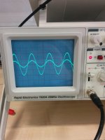
I set it up using a oscilloscope and function generator, however when testing the amplifier I have no idea what I am looking for, and the same goes for testing the amplifier with the crossover. the crossover is designed to spilt the frequency at 4000Hz. I will include some pictures I took when I was testing the amplifier for reference.
Thanks
For a project at college we have to make a product of our own choice, so I decided to make a bookshelf speaker system. for this I have to make a passive crossover. I've designed it and made it, now I just need to test it. my lecturer said I need a amplifier with it, so I've used one I made last year. (I'm not sure why I need one so if you can tell me why that would be brilliant)
I set it up using a oscilloscope and function generator, however when testing the amplifier I have no idea what I am looking for, and the same goes for testing the amplifier with the crossover. the crossover is designed to spilt the frequency at 4000Hz. I will include some pictures I took when I was testing the amplifier for reference.
Thanks
Attachments

It would probably help if you posted the crossover diagram. You need the amplifier to drive the crossover with some real voltage and then observe the voltage across the two (I'm assuming its a two way speaker) drivers and make sure each receives the correct part of the spectrum.
So you need it all wired up with the actual speakers to be able to test it.
So you need it all wired up with the actual speakers to be able to test it.
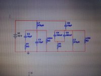
Ahh okay thanks. the college provided me with a 8 ohm resistor to use instead of my speakers, so should I use those? and yes it is a 2 way crossover. I've include a word file with a picture of the crossover design, I've mis-labelled the high and low on the diagram so I apologise about that.
Attachments
That looks quite sophisticated. The actual speakers have very different properties compared to a simple 8 ohm resistor, specifically the inductance of the drive units and their 'impedance' which will vary with applied frequency. At a basic level though you can still demonstrate that the crossover works OK with resistors.
Speaker design and crossovers aren't really my field of expertise if I'm honest... what I'll do is move this over to the Multiway Forum where there is more expertise on this kind of stuff")
Speaker design and crossovers aren't really my field of expertise if I'm honest... what I'll do is move this over to the Multiway Forum where there is more expertise on this kind of stuff
Well ( I'm no expert too but...) the goal is to make something that sounds-and it will .
The fact that loudspeakers are not resistors but they are called "complex loads" should suggest that something else's going on. There are electrical and mechanical parameters, thermical and eventually since they are transducers, there's the air which is resistive too...sorry, it's an impedance ( Z) too.
So the real goal is to make something that produces sound in a manner that nothing is added or lost. Well, there's the room ( when considering the home hi-fi branch of sound reproduction ) that has its modes of vibration either... and naturally there's all the chain preeceding the loudspeaker and the amplifier is directly connected to the LS !
It's called transfer function, nah ?
Usually the beginners in this field are adviced not to follow textbook calculators: indeed you'll seldom see that for a 2nd order filter the coils and the inductors to have the same values, because tweeters and woofers are different beasts ! The latter has more mass, excursion etc and "see" different air Z
...and so on...
Ahh okay thanks. the college provided me with a 8 ohm resistor to use instead of my speakers, so should I use those? and yes it is a 2 way crossover. I've include a word file with a picture of the crossover design, I've mis-labelled the high and low on the diagram so I apologise about that.
Hi,
Its a textbook x/o with zobels on both drivers and
no driver EQ, BSC or relative driver attenuation.
Using 8R loads to test it you need to add driver inductance
to the test loads to reflect the zobel values, then everything
will measure hunkydory, but still be very wrong in reality.
rgds, sreten.
The V1 voltage source should be AC, not DC.
Last edited:
Yes. How can the OP make something he doesn't understand. Using a SPICE MODEL would be closer to reality than a 8R resistor with a different new set of problems. No speaker driver measures 8 for Re anyway. It's just a way of faking something that is not going to work as intended. OP (racer), you have to deconstruct your technically filled mind first... to start with speakers, they are very easy and not complicated as you intend.but still be very wrong in reality.
Also as a note, look for the output of the driver. It is not a straight line but much more or similar to a bell shaped (attenuations), for lack of a better word.
In one word the (specific) crossover works only with a specific driver(s) (parameters). Get used to that (them).
For the E-model of the speaker driver look under Advanced Parameters below.
SS 18W/8545-00 pdf
Loudspeaker Driver Acoustical and Electrical Models
The pic of the oscilloscope in the OP indicates there are two traces. I presume this is a dual trace oscilloscope.
To test the XO, you need to hook up the probes to the amp outputs (Vin) to measure the sine wave voltage on the scope. Take the second set of probes and place them across the 8 ohm dummy load (Vout) and compare the traces. I suggest you run the comparisons at 1 kHz, 4 kHz (xo point) and 7 kHz and compare the sine wave plots and take pics of the scope screen for a record of your results.
The problem with a dummy load is it's not a reactive load like a real woofer or tweeter would have so your results may not truly reflect your design.
For best results, don't use a dummy load. Use the drivers in your speaker design if you have them and measure their dB SPL output converted to voltage using a microphone adapted to the scope.
Last edited:
I would recommend down loading free speaker testing software like ARTA or speaker workshop. These use a computer and it's sound card to preform measurements. It can be used to measure the filter slopes of the crossover and present it on grafs. The substitution of the speakers with the 8 ohm resistor removes the need of the zobel network and will actually affect the filter function.
For best results, don't use a dummy load. Use the drivers in your speaker design if you have them and measure their dB SPL output converted to voltage using a microphone adapted to the scope.
Now that would be a good experiment, except that then he also needs an anechoic chamber. Presumably the test signal from the function generator that he is working with is a continuous sine wave.
These days working with software simulation is going to be a lot more instructive than what the OP is doing. Anyway the software simulation would be a good prelude to the actual construction and testing. For example with software simulation it would be a lot easier to test whether or not the Zobel networks are doing any good than maybe constructing a network of resistors, capacitors and inductors approximating a speaker load.
Sorry but you need to read better the T&C. Arta is shareware, if you want to use all functions (basically save project files) you need a license, otherwise not, because you can run it in demo mode. I use it in demo mode, can save graphs and frd files without problems.Sorry ARTA is not free
Ralf
Now that would be a good experiment, except that then he also needs an anechoic chamber. Presumably the test signal from the function generator that he is working with is a continuous sine wave.
Anechoic chamber not needed. NF mic'ing at low amp volume is all that is needed.
Anechoic chamber not needed. NF mic'ing at low amp volume is all that is needed.
Near field measurement is only accurate up to a rather low frequency depending on the diameter of the woofer. In a two-way system, the crossover frequency is going to be well above that frequency and anyway in the region of the crossover frequency, both the tweeter and the woofer contribute to the intensity of the acoustic output. You must measure far-field.
- Status
- This old topic is closed. If you want to reopen this topic, contact a moderator using the "Report Post" button.
- Home
- Loudspeakers
- Multi-Way
- Help needed for testing crossover