The KLH 5 Crossover Treatise – Randall Peede, Camarillo, CA
I recently restored a pair of KLH Model 5 loudspeakers for a client. What I found surprised me and so I’m passing it on. I worked on Serial #’s A50515788 and A50515786, close enough to sequential for me.
I rebuilt the crossovers one at a time for testing comparison. Both crossovers had bad caps. I used Solen’s from Parts Express. I replaced the tweeters with the best I could find on eBay and tested them.
The old tweeters were fried, which is not unusual on this model, and I found out why. After disassembly, I put a crossover on my spectrum analyzer with a full-range, pink-noise source. With the left, 3-position crossover knob (marked 2500-700 CPS) set to the full counter-clockwise, “Decrease” position, the tweeter was receiving full bass response in addition to tweeter response. There was also a -8dB saddle in the middle. The center position (“Normal”) and right position (“Increase) were OK. The right-hand switch (“Above 7000 CPS”) had no effect on the tweeter/bass anomaly. Gee, I wonder why they fry tweeters.
Now let’s look at the boring details. First I’ve seen some reference to metal back plates on the crossover. These are plastic. Next there’s the schematic available online which does not match the actual product. The midrange connections on the crossover measured fine in any switch position as did the woofer.
The left rotary switch is a 12 position model with three sliding plates controlling the connections. The right rotary switch is also a 12 position switch of which only seven connections are used with two sliding plates. So we have lots of permutations to trace.
Without a correct schematic, I started drawing one. I started from the tweeter output side and then from the main inputs. First I found a loop that went nowhere. Then it got weird. I stopped. If I was going to do a science project or thesis, I could finish this analysis, but the point here was to restore/fix.
There were three possibilities: 1. Start from scratch and redesign the crossover – no., 2. Design an add-on external circuit – I did it, but while the bass was gone from the tweeters, the effect was incorrect for other settings. 3. Put a sign on the back of the speaker that says Never, ever use this position (with an arrow). It will destroy your tweeters! Like I said, this wasn’t a science project, so I chose #3.
I did a full-range measurement of both assembled speakers using a calibrated microphone and verifying the amplifier’s flatness of response. Both speakers look great on the spectrum analyzer. I did not test the dreaded “Decrease” position. This whole process consumed about 30 hours, including lying in bed at night staring at the crossover and tracing in my mind. An interesting experience.
Without a correct schematic, I started drawing one. I started from the tweeter output side and then from the main inputs.
KLH 5 Schematic | The Classic Speaker Pages
Thank you, but it still doesn't match the actual product
Thank you, I appreciate your response, but neither factory schematic matches the actual product that was in front of me. The photos are of the metal backed ( they look earlier) crossovers. Mine were plastic.
Best Regards
Thank you, I appreciate your response, but neither factory schematic matches the actual product that was in front of me. The photos are of the metal backed ( they look earlier) crossovers. Mine were plastic.
Best Regards
neither factory schematic matches the actual product that was in front of me. The photos are of the metal backed ( they look earlier) crossovers. Mine were plastic.
Maybe someone "rebuilt" them.
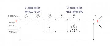
According to KLH model 5 schematic from 1969, there is nothing
unusual about the decrease knob position. Rotating SW1 2500-7000 Hz
clockwisely, switches two 4 uF in series, parallel with addition of
adding 0,4 mH as second order filter.
SW2 increases spl of only very high frequencies.
unusual about the decrease knob position. Rotating SW1 2500-7000 Hz
clockwisely, switches two 4 uF in series, parallel with addition of
adding 0,4 mH as second order filter.
SW2 increases spl of only very high frequencies.
Attachments
What "I" think needs to be addressed with any KLH 5, ( that I have not yet found on line ), is OTHER very simple and logical changes one can do to enhance the KLH's performance.
First of all, the internal wiring of the entire crossover, and certainly its leads from the crossover to the drivers, are VERY HIGH LOSS, and low in quality.
I will replace my KLH 5s' leads with 12 AWG Military copper stranded, silver plated wire, and, I will likely, for sure, use TWO runs in parallel to the woofers ( equals 9 AWG ). One can source such 12 AWG high-quality teflon-coated wire, for about 70 cents a foot, from Steve at Apex Junior, on line.
A second cost effective mod that I will do is to eliminate both of the two Cut-Normal-Boost switches, with their possible / probable contact issues and losses. The best-sounding switch and contact, is to have NONE at all !!!
This will require TRACING the circuit, in the normal or middle ( flat ) position for each switch, and SIMPLFY the crossover path, by eliminating these two signal-degrading switches and their contacts totally !!
Of course, one can employ multiple film crossover capacitors, and better wire wound resistors, maybe even lower DCR chokes. But the first two suggestions above, I've
(a) never seen discussed,
(b) are "almost" for free, and
(c) it could / should yield a significant listening improvement.
I personally don't think anyone has heard fully what a KLH 5 can do, until we execute the Model Five as I have suggested herein.
if anyone has done these changes, and listened to them already, please post your before and after listening experiences !!
I used to own / run, single and double pairs of KLH9s, back in the 1970s.
Thanks.
Jeff
Last edited:
- Status
- This old topic is closed. If you want to reopen this topic, contact a moderator using the "Report Post" button.
- Home
- Loudspeakers
- Multi-Way
- KLH Model 5 Crossover Restoration