Here a SEAS L16RN-SL using a Linkwitz Pluto type mounting and a Vifa NE180W-04 suspended vertically above the woofer is used for exploring cardioid sound field. The Vifa (Tymphany) is sold as “full range woofer”. As tested by manufacturer, doubtless done in a baffle, on axis performance looks impressive to >10kHz, with rapid roll off beyond 2kHz off axis, and recommended use 40Hz-4kHz.
The SEAS woofer as mounted is highly omni directional somewhat beyond 1kHz; based on prior knowledge and a brief measurement survey the driver is used with steep crossover at 2kHz.
The Vifa driver was measured extensively to get a good grasp of its performance characteristics. A series of measurements from front and back at 27”suggest an acoustic source that starts at neck of driver cone. The driver was rotated in vertical plane through the cone’s neck at 5° intervals. Dual channel sweeps where used with one for loop back timing reference and the other for response measurement. The use of timing reference and use of measuring tape combined together helped in keeping highly fixed measurement distance. Front of driver on axis is 0°. Backside measurements were made from 90-180 degrees and front side measurements from 0-60 degrees(Yes, 75° is missing). Overlays of results indicate highly dipole radiation pattern to 2kHz. Measurements remain well organized to 4kHz. Above 4kHz cone geometry takes over.
The 0° and 15° degree shows some plausible potential use of the driver full range to 14-15kHz
Overlays 0-60 degrees:

Overlays 90-180 degrees:

A choice was made to first explore driver alignment with Vifa rim centered above SEAS dust cap. This puts Vifa acoustic center about 1” behind SEAS acoustic center. 1” represents ½ to ¼ wavelengths about an order of magnitude shorter than 2kHz upper range of driver overlap. Driver effective diameters at 1-2kHz and apparent acoustic centers in this range are likely larger factor in polar pattern formed by superposition of each driver’s polar pattern.
Vifa driver connected as microphone with 220Hz signal to SEAS was used in finding driver position minimizing driver interaction. Vifa rim above center of SEAS dust cap produced best null, indicating equal energy delivery to front and back of Vifa from SEAS. Vifa rim is 1” above SEAS driver’s dust cap.
Great results were obtained for Pluto Clone with 2” tweeter when reference measurements from single measurement point located 9” from face of tweeter, and slightly off of tweeter axis. Direct to reflected ratio is sufficient for direct inversion using Kirkeby method in achieving equalization filters. With Pluto Clone development measurements from 2’ contained too many reflected signals, mostly floor/ceiling reflections, leading to great group delay at specific frequencies. Application of Kirkeby to such measurements leads to extreme ringing at certain frequencies, readily heard when inverse filter is convolved with sweep or music signals. This type of filter is only valid at measurement location. Anticipating this and dipole behavior of reinforcement/cancellation as wavelengths become shorter than driver diameter, and tempered by cone geometry influence near/far, a single measurement point for drivers was chosen about 12” from driver centers, and chosen 15° off axis of Vifa so to capture the flatter high frequency response. Direct use of measurements with Kirkeby resulted in ringing behavior. Application of Blackman-Harris 7 term window via REW with 15ms setting prior to Kirkeby produced working results. Windowing of result to 15ms still provides low frequency information within 1dB of large window results whilst suppressing unwanted reflections. Kirkeby filters applied to respective drivers flatten their responses.
Woofer filter is band pass filtered to 50Hz-2kHz, tweeter is filtered 200Hz-15kHz. Results sum over 200Hz-2kHz range. Secondary filter is used to shelve each driver’s response down 6.02dB across 200Hz-2kHz overlap region. Applying Kirkeby inverse transform to sum of 200Hz high pass filter with 2kHz low pass filter generates the secondary filter. Result is flat sum with monopole behavior 50Hz-200Hz, cardioid behavior 200Hz-2kH, and dipole behavior above 2kHz that is shaped by cone geometry.
Raw Crossover:

DSP:
J River Media Player is used for playback of sweep signals, convolution of sweeps with filter kernels, and recording of microphone responses. Previous testing finds software bit perfect. Here are frequency response overlays of measured results 0-180 degrees at intervals of 15 degrees. Microphone is placed 9” from edge of woofer pipe at height of tweeter axis. Tip of microphone is sighted through to protractor ruling around pipe top, and against center of woofer dust cap for achieving rotational alignment. Sweeps are exponential 2Hz-22050Hz with 262144 samples. A series of four sweeps with ½ seconds of silence are used as stereo track. Signal polarity of 2nd sweep of track 1 (woofer) and 3rd sweep of track 2 (tweeter) have polarity inverted. Resultant test sequence is: 1) normal woofer with normal tweeter, 2) inverted woofer with normal tweeter, 3) normal woofer with inverted tweeter, and 4) is repeat of 1). This format allows for sums and differences for verifying integrity of data and extracting images for solo woofer and solo tweeter responses. The four sweep periods are 284194 samples. Each isolated block is convolved with inverse sweep, obtaining impulse response. Resultant IR data are ported into REW for generating overlays of frequency responses.
Using Room EQ Wizard software, frequency response overlay views of 13 measurements 0-180 degrees for normal woofer polarity and for reverse woofer polarity is set up. Flat response region for 0 degree normal woofer polarity measurement across 300Hz-800Hz is offset to 0dB and all other results shifted by same offset. The same plot colors are used for corresponding rotation angles for both overlay views:

With woofer polarity reversed:

Monopole behavior is seen centered at about 55Hz.
Strong cardioid behavior is seen 200Hz-1kHz, indicative both of good monopole driver behavior and of good dipole behavior.
Measurements with microphone at reference point:

The SEAS woofer as mounted is highly omni directional somewhat beyond 1kHz; based on prior knowledge and a brief measurement survey the driver is used with steep crossover at 2kHz.
The Vifa driver was measured extensively to get a good grasp of its performance characteristics. A series of measurements from front and back at 27”suggest an acoustic source that starts at neck of driver cone. The driver was rotated in vertical plane through the cone’s neck at 5° intervals. Dual channel sweeps where used with one for loop back timing reference and the other for response measurement. The use of timing reference and use of measuring tape combined together helped in keeping highly fixed measurement distance. Front of driver on axis is 0°. Backside measurements were made from 90-180 degrees and front side measurements from 0-60 degrees(Yes, 75° is missing). Overlays of results indicate highly dipole radiation pattern to 2kHz. Measurements remain well organized to 4kHz. Above 4kHz cone geometry takes over.
The 0° and 15° degree shows some plausible potential use of the driver full range to 14-15kHz
Overlays 0-60 degrees:
Overlays 90-180 degrees:
A choice was made to first explore driver alignment with Vifa rim centered above SEAS dust cap. This puts Vifa acoustic center about 1” behind SEAS acoustic center. 1” represents ½ to ¼ wavelengths about an order of magnitude shorter than 2kHz upper range of driver overlap. Driver effective diameters at 1-2kHz and apparent acoustic centers in this range are likely larger factor in polar pattern formed by superposition of each driver’s polar pattern.
Vifa driver connected as microphone with 220Hz signal to SEAS was used in finding driver position minimizing driver interaction. Vifa rim above center of SEAS dust cap produced best null, indicating equal energy delivery to front and back of Vifa from SEAS. Vifa rim is 1” above SEAS driver’s dust cap.
Great results were obtained for Pluto Clone with 2” tweeter when reference measurements from single measurement point located 9” from face of tweeter, and slightly off of tweeter axis. Direct to reflected ratio is sufficient for direct inversion using Kirkeby method in achieving equalization filters. With Pluto Clone development measurements from 2’ contained too many reflected signals, mostly floor/ceiling reflections, leading to great group delay at specific frequencies. Application of Kirkeby to such measurements leads to extreme ringing at certain frequencies, readily heard when inverse filter is convolved with sweep or music signals. This type of filter is only valid at measurement location. Anticipating this and dipole behavior of reinforcement/cancellation as wavelengths become shorter than driver diameter, and tempered by cone geometry influence near/far, a single measurement point for drivers was chosen about 12” from driver centers, and chosen 15° off axis of Vifa so to capture the flatter high frequency response. Direct use of measurements with Kirkeby resulted in ringing behavior. Application of Blackman-Harris 7 term window via REW with 15ms setting prior to Kirkeby produced working results. Windowing of result to 15ms still provides low frequency information within 1dB of large window results whilst suppressing unwanted reflections. Kirkeby filters applied to respective drivers flatten their responses.
Woofer filter is band pass filtered to 50Hz-2kHz, tweeter is filtered 200Hz-15kHz. Results sum over 200Hz-2kHz range. Secondary filter is used to shelve each driver’s response down 6.02dB across 200Hz-2kHz overlap region. Applying Kirkeby inverse transform to sum of 200Hz high pass filter with 2kHz low pass filter generates the secondary filter. Result is flat sum with monopole behavior 50Hz-200Hz, cardioid behavior 200Hz-2kH, and dipole behavior above 2kHz that is shaped by cone geometry.
Raw Crossover:
DSP:
J River Media Player is used for playback of sweep signals, convolution of sweeps with filter kernels, and recording of microphone responses. Previous testing finds software bit perfect. Here are frequency response overlays of measured results 0-180 degrees at intervals of 15 degrees. Microphone is placed 9” from edge of woofer pipe at height of tweeter axis. Tip of microphone is sighted through to protractor ruling around pipe top, and against center of woofer dust cap for achieving rotational alignment. Sweeps are exponential 2Hz-22050Hz with 262144 samples. A series of four sweeps with ½ seconds of silence are used as stereo track. Signal polarity of 2nd sweep of track 1 (woofer) and 3rd sweep of track 2 (tweeter) have polarity inverted. Resultant test sequence is: 1) normal woofer with normal tweeter, 2) inverted woofer with normal tweeter, 3) normal woofer with inverted tweeter, and 4) is repeat of 1). This format allows for sums and differences for verifying integrity of data and extracting images for solo woofer and solo tweeter responses. The four sweep periods are 284194 samples. Each isolated block is convolved with inverse sweep, obtaining impulse response. Resultant IR data are ported into REW for generating overlays of frequency responses.
Using Room EQ Wizard software, frequency response overlay views of 13 measurements 0-180 degrees for normal woofer polarity and for reverse woofer polarity is set up. Flat response region for 0 degree normal woofer polarity measurement across 300Hz-800Hz is offset to 0dB and all other results shifted by same offset. The same plot colors are used for corresponding rotation angles for both overlay views:
With woofer polarity reversed:
Monopole behavior is seen centered at about 55Hz.
Strong cardioid behavior is seen 200Hz-1kHz, indicative both of good monopole driver behavior and of good dipole behavior.
Measurements with microphone at reference point:
Last edited:

Andrew,
Very interesting.
I don't think I missed it, but in this case you've suspended (strings from the ceiling?) the Vifa driver completely open-air with no structure attached to it at all?
How transferrable do you think the results would be with other 6.5" drivers of similar construction?
I'm not sure I have the computer horsepower to implement a similar setup. You're running on a desktop machine (maybe Windows 7 64-bit) and incurring quite a bit of latency?
Cheers,
Dave.
Hi Barleywater,
Impressive work all around!
You seem to be getting ideal performance in your overlapping dipole/monopole region. Well above that region you are doing as well as the full range driver is capable of (it rolls off then comes back to life off axis). I wonder if there is any way to improve the transition between the two regions? Is a hard transition mandatory?
I assume a reasonable phase match of the of the dipole and monopole are required for ideal polar patterns. I know you displaced the drivers to get good time allignment of the two. I wonder if a slow transition could be phase compensated?
Anyhow, interesting stuff.
David
A 1/4" steel rod was fitted to one of Vifa driver basket arms with small hose clamps and a counter balance. A small hose clamp at pivot point was used with hook formed by clamp's excess tail catch top tube of folding music stand:

Filters used are about 22k taps. Computational power for convolution is not an issue. I've run 6x 32k tap filters with Pentium III 500MHz laptop.
For music playback latency is non issue, other than lag of volume control. If I am not mistaken, JRiver Media software has facility for delaying video for synching.
In the case of this setup intention is to demonstrate feasibility of this approach. Filters use up a lot of dynamic range. SPL with heavy bass is quite limited. Scale up would likely use 8-10" drivers and second pairing of smaller monopole/dipole pair; the trick is where to put second monopole.
Goal in this case is to maximize cardioid pattern in fundamental range of most music and voice.
SEAS driver has nasty metalic sound above 2kHz. Widening the overlap upwards promotes metalic sound; and driver pair becomes less coincident. Widening overlap downwards degrades cardioid pattern to hyper/super cardioid with backside lobes.
Impulse response:

Frequency response and phase:

Filters used are about 22k taps. Computational power for convolution is not an issue. I've run 6x 32k tap filters with Pentium III 500MHz laptop.
For music playback latency is non issue, other than lag of volume control. If I am not mistaken, JRiver Media software has facility for delaying video for synching.
In the case of this setup intention is to demonstrate feasibility of this approach. Filters use up a lot of dynamic range. SPL with heavy bass is quite limited. Scale up would likely use 8-10" drivers and second pairing of smaller monopole/dipole pair; the trick is where to put second monopole.
Goal in this case is to maximize cardioid pattern in fundamental range of most music and voice.
SEAS driver has nasty metalic sound above 2kHz. Widening the overlap upwards promotes metalic sound; and driver pair becomes less coincident. Widening overlap downwards degrades cardioid pattern to hyper/super cardioid with backside lobes.
Impulse response:
Frequency response and phase:
Are these measurements truely of group-delay or just convolutions to compliment and correct for frequency response to be flat?
Is the group-delay flat as well?
THx-RNMarsh
Is the group-delay flat as well?
THx-RNMarsh
Convolution is used in JRiver Media player to apply correction filters to source file, so music and test signals are treated the same.
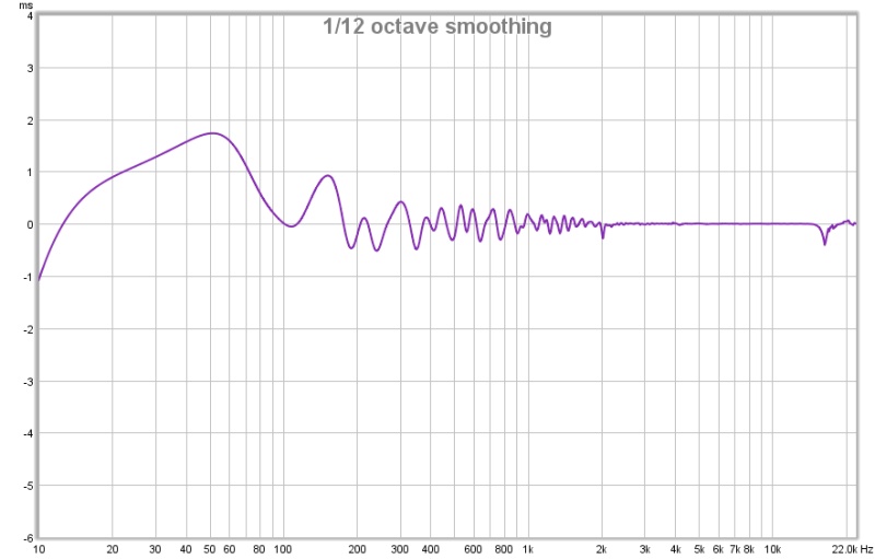
This is the measured GD using 110ms Blackman-Harris 7 term window.
Thanks for the interest.
-Andrew
This is the measured GD using 110ms Blackman-Harris 7 term window.
Thanks for the interest.
-Andrew
Barleywater, those are outerworldy filterslopes and ditto results. I am digging into FIR filtering, and one of the innate disadvantages appears to be pre-ringing. Is this something to worry about in your experience?
When delving into FIR filters I initially worried a lot based on all the commotion an IR waveform causes when people see waves to the left of where all the high frequency energy is centered. It only drove me to find out first hand what all the flap is about.
I strive for driver alignment including phase and amplitude match across overlap region, and getting driver centers within 1/4 wavelength for XO overlap frequencies. For vertically oriented driver centers worst response is on vertical axis. FR has 3dB dip there, and maximal ringing. For drivers XO at 1kHz ringing is 0.25ms.
Difference in sound for IIR based transients on vertical v horizontal axis are discernible in direct comparison by A/B of recordings or simulations. I don't generally listen on vertical axis.
My initial interest was to get cardioid response from 200Hz-1kHz, and attempted 2kHz to see how the system deviated. The reverse woofer polarity 3dB peaking in the polars at 1.5kHz is do primarily to 1/4 wave behavior of the two drivers.
The dipole driver location above the woofer was chosen by hooking the dipole up as a microphone, playing a low frequency tone through the woofer, and adjusting the dipole location for minimizing picked up signal.
I'm looking forward to what you dig up.
When delving into FIR filters I initially worried a lot based on all the commotion an IR waveform causes when people see waves to the left of where all the high frequency energy is centered. It only drove me to find out first hand what all the flap is about.
....
I'm looking forward to what you dig up.
That is exactly what has been putting me off, but if I translate your post correctly into Australian, what you are saying is "no worries, mate".
I don't think I have any option other than getting into this technology. I can get speakers with an analog active crossover to within +/- 1.5 dB, with only corrections for delay and baffle step. This is not bad at all, but the newest speakers that come out are as flat as a salt plane. It is really amazing to see how, using this technology, you were able to draw a funky contraption of speakers as straight as you did.
An important thing I learned for your post is that I do not need to invest right away in a MiniSharc or another FIR capable DSP, but that I can take my first baby steps using hardware I already have - a discarded XP PC. Since you only use two channels in your experiment, I suppose you are using the stereo outputs on your PC. However, I would like to play in stereo and need three channels per speaker, so that calls for a solution. Perhaps a multi channel sound card will do the trick. Do you, or readers of this thread, have hands on experience with such a setup?
As soon as I get something that works I'd be most happy to share my results.
For soundcards all most any multi-channel sound card works. My first success was with above mentioned PIII 500MHz laptop, and a Sound Blaster Extigy USB with 5.1 surround sound capability.
My main card is Roland Octa-Capture with 8 channels of analog output.
Last year I picked up a Behrigner FCA610, $200. Only complaint is that its output levels are a bit lower than the Octa-Capture's.
I've even verified ability to control all outputs of a Diamond 7.1 channel USB; about as inexpensive as possible. I have not used this in a system, but wanted to explore possibility.
Barleywater, great work! I have a question. Imagine I have quite a few 4" midrange/fullrange drivers. Would the arrangement work to achieve cardioid behavior if the bottom monopole consisted of two speakers? One before the dipole, and one behind. Both in phase off course.
Furthermore, what if dipole on top would consist of MTM dipole? I suppose you know what I mean. If not, I can draw it. Thanks.
Furthermore, what if dipole on top would consist of MTM dipole? I suppose you know what I mean. If not, I can draw it. Thanks.
Barleywater, your thread has helped me a lot. I just did Holmimpuls->RePhase->Jriver for small two way speakers, and presto, it is so easy it takes the fun out of learning. This works for recorded work. But how did you get your measuring signal convolved? Is there is trinket that you could introduce just before the pc audio driver, so that all sound sent to your speakers will be convolved, regardless of the program of origin?
Last edited:
Vac - I've been using a pc based system with J River for 3-4 years now. Currently active 2.5 way speakers + subs. I use a studio audio interface for a multichannel dac.
There's a few ways to route all the pc audio through MC's dsp. One is the loopback feature which must be opened every time you want to use it. They also now have a wdm driver that does the same and works automatically when setup right. Unfortunately it isn't stable enough in my system for critical listening/measurements. There should be info about these methods on their wiki. You could also use ASIO bridge.
There's a few ways to route all the pc audio through MC's dsp. One is the loopback feature which must be opened every time you want to use it. They also now have a wdm driver that does the same and works automatically when setup right. Unfortunately it isn't stable enough in my system for critical listening/measurements. There should be info about these methods on their wiki. You could also use ASIO bridge.
........J River Media Player is used for playback of sweep signals, convolution of sweeps with filter kernels, and recording of microphone responses.......
The player allows simultaneous playback of file with convolution and live recording to file.
Usually I bring response sweeps into Cool Edit and convolve them with the appropriate inverse sweep to obtain impulse responses.
It is also possible with JRiver: Inverse sweep with proper normalization is loaded as convolution filter, "diskwriter" is selected as output device. Playing response sweep then generates file containing IR. This still needs trimming to get into REW, so editor is still needed.
I don't use REW with loopback using JRiver output as input because with long filters (16k-32k taps) REW stops capture before convolved sweep finishes, cutting off the high frequencies. I use 262k long sweeps and larger for better S/N, and for better separation of distortion components from start of the lR. Also with short sweep second harmonic's impulse decay tail aliases into linear IR.
Conveniently Holm Impulse will save test sweeps and its inverse and these may be used with JRiver technique for IR measurements.
For 2-way design test sweep is loaded into stereo track in one channel, a silence of know length added at end (allowing capture of high frequency decay after sweep finishes), and then at new track end a second copy of sweep is placed in the second channel, followed by adding a finishing block of silence to the end. With known length of sweep and silences, the resulting mono response recording containing separate sweeps for woofer and tweeter is edited into stereo sweeps with perfect time alignment. Each track is convolved with inverse sweep resulting in perfectly aligned IR. Sum of IR predict system response, and the difference of the IR predicts reverse null behavior.
The basic method here allows use of single microphone and periodic signals to get time aligned results, making USB microphones useful. Time aligned measurements in REW with USB microphone requires measuring drivers independently and together, and bumping the solo responses around until observed frequency response and phases for regions outside the crossover overlap region match up. REW allows IR to be shifted by increments as small as 0.1 microsecnds.
Barleywater, great work! I have a question. Imagine I have quite a few 4" midrange/fullrange drivers. Would the arrangement work to achieve cardioid behavior if the bottom monopole consisted of two speakers? One before the dipole, and one behind. Both in phase off course.
Furthermore, what if dipole on top would consist of MTM dipole? I suppose you know what I mean. If not, I can draw it. Thanks.
With MTM dipole horizontal or vertical with monopole as two drivers has potential for cardioid pattern. Linear excursion is limiting factor in how low the cardioid pattern can go.
A good set of polar plots for MTM dipole in vertical and horizontal orientation would yield information on how high the cardioid pattern may go. Beaming of monopole also limits cardioid performance.
I found this thread when looking for some examples of a dipole+monopole to form a cardiod. Interesting stuff...
It might be helpful to show what is going on with the pattern the response was plotted for a few select frequencies between 100Hz and 1.5kHz in polar form. I can do that if you are interested (drop me a PM) using a new plotting tool I am developing that can take multiple single-angle datasets of SPL vs frequency and then produce and plot the SPL vs angle data in polar coordinates like the attached plot.
I'm trying to see if I can use some existing 12" drivers to create a cardoid pattern between about 200Hz and 800Hz (or to 1kHz if possible). These are significantly larger than the drivers you are using, but I have them on hand so I might as well try to see what I can do with them as well as the ins and outs of this way to generate a cardioid type response. MY guess is that they will require too great a separation to work sufficiently high in frequency for my needs, but I might as well try and measure. If anyone has thoughts or experiences to share on the feasilbility (or infeasibility) of using 12" drivers for this I would love to read them.
Also, I was wondering if there was anything special about your extremely steep FIR filters. Why did you choose to use them? I didn't see any explanation of that in the writeup.
I am interested and I will look for future posts in this thread. Thanks for posting your results.
Attachments

Reading off data from presented plots for use in polar plot is straight forward. Feel free to do this and post results.
Here is big picture of same data set using 3 cycle frequency dependent windowing with cursor located at 1514Hz. dB data in legend is for 1514Hz.

Opening picture in own tab will make reading data off much easier.
With 12" drivers it is expected that plots bunch up around 700Hz-800Hz.
Steep FIR filters at low frequency were to reduce excursion demand on dipole driver.
Steep FIR at 2kHz was to see what sharp transition from cardioid to dipole pattern looks like.
Here is big picture of same data set using 3 cycle frequency dependent windowing with cursor located at 1514Hz. dB data in legend is for 1514Hz.
Opening picture in own tab will make reading data off much easier.
With 12" drivers it is expected that plots bunch up around 700Hz-800Hz.
Steep FIR filters at low frequency were to reduce excursion demand on dipole driver.
Steep FIR at 2kHz was to see what sharp transition from cardioid to dipole pattern looks like.
Bumping an old thread, but I really like how these speakers approach the design goals, and would like to work on something similar.
The DSP I have available to me is limited to around 2000 taps per output, but I do have 6x outputs to play with.
I like the idea of cardioid and/or controlled directivity over a wide range, and I have a few drivers around here that I think it'd be interesting to play with.
Since we can throw linear-phase crossovers at everything, how about this:
- 6" monopole driver, sealed/ported/TL for LF reinforcement
- 2-way dipole. 8" lower-mid and 3-4" full-range unit. Cross between them at, say, 500Hz.
I think that would improve headroom towards the bottom of the cardioid band.
For the upper end of the cardioid band, I think a monopole driver with better HF performance (or another 2-way system) would be in order.
Some drivers I have around that might be fun to try:
2x Fostex FE166En (monopole?)
2x Fostex FE126E (HF dipole)
2x unknown 8"s (LF dipole)
I figure the Fostex 6" with a whizzer cone will have reasonably good full-range performance compared to a dedicated midbass. Could probably run up to a few kHz with reasonable off-axis performance.
I'd then add a (non-FIR-processed) subwoofer to cover the low stuff. The Fostex 6" units won't produce a lot of bass, but with a bit of EQ will probably meet a sub.
Chris
- Status
- Not open for further replies.
- Home
- Loudspeakers
- Multi-Way
- Cardioid as sum of monopole and dipole speakers: