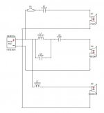
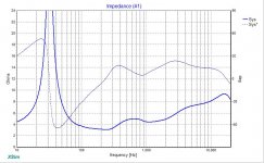
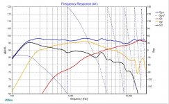
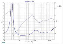
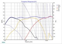
I'm finally getting around to learning to design passive crossovers. I've got a project in mind, but at first I just thought I would try designing crossovers using drivers for which I can download the FRD and ZMA files from the Internet. I'm using XSim as the design software. Hopefully this will let me gain some experience and learn some lessons before embarking on a project that I will invest money in. Attached is a circuit and the resulting Frequency and Impedance curves. I'm very interested in feedback about this. Did I do it correctly? What did I miss?
Drivers:
Seas 27TDFC (1" Dome, 6ohm)
Dayton RS52AN-8 (2" dome, 8ohm)
Scan-Speak 18W4531A (7" Woofer, 4ohm)
Drivers:
Seas 27TDFC (1" Dome, 6ohm)
Dayton RS52AN-8 (2" dome, 8ohm)
Scan-Speak 18W4531A (7" Woofer, 4ohm)
Attachments
I see some problems.
1) how can you have 95+ dB with only 2.8V? are the frd files correct?
2) frankly I wouldn't touch a speaker with the response like the one posted, as it will severely limited in power handling (and the woofer breakup is not tamed at all): first order crossover can be used on a very limited number of drivers.
3) when using a frd file you should know the condition where the driver has been measured, because the baffle geometry plays a role in the FR. Assuming you find frd of a driver calculated on an infinite baffle you should modify it by calculating the effect of the actual baffle and the driver placement onto the baffle. This could be accomplished by using some software like the baffle diffraction simulator (excel based), and then extracting the minimum phase.
Ralf
Great. Thank you both so much for your feedback. I've got some questions to help me learn:
Why does the woofers breakup not being tamed matter if it doesn't peak the overall system response?
I don't think the measurements taken for these drivers were calibrated for absolute sensitivity. They all came from the same source so I think their relative sensitivity is accurate (hope so). I wouldn't draw any conclusions from them about the actual sensitivity of the resulting speaker.1) how can you have 95+ dB with only 2.8V? are the frd files correct?
What limits the power handling? The tweeter's response below the tweeters FS?2) frankly I wouldn't touch a speaker with the response like the one posted, as it will severely limited in power handling (and the woofer breakup is not tamed at all): first order crossover can be used on a very limited number of drivers.
Why does the woofers breakup not being tamed matter if it doesn't peak the overall system response?
I agree. When I design real loudspeakers I intend to measure FR with the drivers on the actual baffle I intend to use. For the purpose of this exercise I didn't bother modeling any particular baffle because I am more focused on learning how to put the passive crossover network together. But again, I agree, I will use FR data from drivers in the actual baffle when doing a real design.3) when using a frd file you should know the condition where the driver has been measured, because the baffle geometry plays a role in the FR. Assuming you find frd of a driver calculated on an infinite baffle you should modify it by calculating the effect of the actual baffle and the driver placement onto the baffle. This could be accomplished by using some software like the baffle diffraction simulator (excel based), and then extracting the minimum phase.
Why does the overlap cause poor off-axis response? Is it because the off-axis response of the 7" woofer drops off at high frequencies?Your low slope crossovers have resulted in huge overlap amongst the drivers. This guarantees your off-axis response will be very messy.
Why does the overlap cause poor off-axis response? Is it because the off-axis response of the 7" woofer drops off at high frequencies?
You have multiple Octaves where 2 or 3 of the elements are too close in strength. If you move up or down from the simulated axis the phase of the individual units will shift and they will cancel rather than add.
Steeper slopes will give a lesser range of overlap and minimize the off axis mess.
Does your simulation software allow you to move your microphone position? It would show off axis issues.
Directivity of the 7" unit is not an issue.
"What limits the power handling? The tweeter's response below the tweeters FS? "
"Why does the woofers breakup not being tamed matter if it doesn't peak the overall system respons Two good beginner questions:
Power handling: any time you "cut" the low frequency feed to a driver gradually (as your 6db/oct filters do), the amount of energy being fed to the driver below its' comfortable range will limit the total power handling of that driver. Either you need to increase the crossover frequency by a lot, or use steeper sloaps.
"Why does the woofers breakup not being tamed matter if it doesn't peak the overall system response?"
Frequency response is "steady state". Cone breakup MAY cause steady-state response to peak, or it may be small enough you don't see it in a chart, BUT it will always cause energy storage in the cone, which will color the output and "smear" transients. Using a "notch filter" can reduce the amount these are triggered, and steeper sloped crossovers will help this a lot.
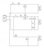
Thanks for the feedback. Rethought the crossover with 2nd order slopes to avoid some of the problems you all pointed out. I'm getting the impression that 1st order slopes aren't very practical. When is it possible to use 1st order slopes?
Anyway, more feedback on this latest iteration is very appreciated.
Anyway, more feedback on this latest iteration is very appreciated.
Attachments
What I want is to aim at a specific slope for the responses, for example LR4 (4th order LR). This is the acoustic slope, and the electrical slope needed to achieve this is generally lower. With that in mind I try to achieve good phase (*) relationship between drivers in the crossover region. A good thing is to plot also the driver's phase together to the FR (and leave out the system phase as is useless).
A mid/tweeter crossover with LR4 slopes and good phase alignment can be usually achieved with a 2nd electrical order on the mid and a 3rd order on the tweeter. A woofer/mid crossover with LR2 slopes can be achieved on the mid with a first order electrical slope if the crossover frequency is the same as the baffle step effect (and the mid can sustain this low electrical slope at this frequency).
What you need to pay attention also is the delay value of the drivers (in xsim). This is because the drivers have different path length to the mic, so you have to calculate this difference, keeping in mind that the more the larger the driver is, the more the sound appears to come from behind the baffle (example 1" for a 6.5" driver **). Even small changes can have huge differences at least for the mid/tweeter crossing. If you want to use your measurements, there is a good document (by Jeff Bagby I think) that explains how to calculate this offset.
Ralf
(*) minimum phase
(**) for a tweeter you can set delay at 0, but don't know what a correct value could be for a mid like yours
Hi wig,
You might want to reconsider using a 4 ohm woofer
in a design like this for an 8 ohm. Practicing higher
order filters sinks the impedance to lower values.
Manufacturers usually install a 4 ohm bassmid
in a 2 way speaker. The main principle of loudspeaker
design you already understand. Keep simulating.
Later you can study the XO point selection process.
A 2" dome midrange would be better off crossed at
600,700 Hz.
Have you managed to resolve boxy sound issues
with in-wall speaker kits?
Last edited:
Hi,
Work your way through all Zaph's designs and
his site and you'll learn a lot : Zaphaudio.com
Learn the FRDtools, Xsim is far too crude.
Also look at Zaph|Audio - ZDT3.5 which is the best
way of using the RS 2" dome, by a country mile.
rgds, sreten.
http://www.parts-express.com/project-gallery-speaker-project-zdt-35
Last edited:
Hi,
Learn the FRDtools, Xsim is far too crude.
Thanks so much for the advice. What makes XSim crude? Is it the lack of box modeling, baffle diffraction, etc? Or is there something missing from the actual crossover circuit design and simulation portion? The reason why I ask is because I actually found the FRDTools to be quite crude.
Thanks so much for the advice. What makes XSim crude? Is it the lack of
box modeling, baffle diffraction, etc? Or is there something missing from
the actual crossover circuit design and simulation portion? The reason
why I ask is because I actually found the FRDTools to be quite crude.
Hi,
The lack of box diffraction is a bit of a killer. If you become
familiar with FRDtools, you can still use Xsim if you want,
by modifying the FRD's according to box diffraction sims.
Lack of different axis is also a problem, but not a show
stopper, with sensible design and good reverse nulls.
I'd study the ZDT3.5 hard, its a tour de force in
sensible driver choice and great x/o design.
It should be built with the tweeters at or
somewhat lower that seated ear height.
rgds, sreten.
Last edited:
I think that xsim is a good program, and could be all you need if you use your own measurements. On the other hand, if you need to simulate something before buying drivers and/or building a cab, then you need to use FRDtools before using xsim (calculating baffle step and diffraction - this is what sreten said).
The only tricky thing in xsim is the delay value, which you need to calculate, whereas in PCD you simply put the xyz values of the driver position.
Ralf
The only tricky thing in xsim is the delay value, which you need to calculate, whereas in PCD you simply put the xyz values of the driver position.
Ralf
")
- Status
- This old topic is closed. If you want to reopen this topic, contact a moderator using the "Report Post" button.
- Home
- Loudspeakers
- Multi-Way
- Learning to design Passive Crossovers (feedback please)