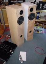
Hello, i started a new 2Way project for my home hifi.
My passion started in the car hifi field. Now i have a pair of Scan Speak 18W/4531-G00 that i used in my old car.
So i decided that it is time to build a new speaker for my home.
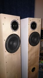
After looking for many projects with this driver and consulting a user of this form i decided to use a 35l bassreflex cabinet.
For the tweeter i used the sb acoustics satori.
Both drivers are 4 ohm drivers.
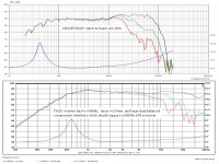
Currently i'am trying to get out the best result by optimizing the crossover.
But already now iam very pleased with the result
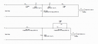
Corssover at the moment is 12db low pass for the woofer and 18db high pass for the tweeter. It was developed by measuring, trying a lot of different components, hearing and simulating. I dont know if its the best but its sound good to me, waiting for some comments thanks
My passion started in the car hifi field. Now i have a pair of Scan Speak 18W/4531-G00 that i used in my old car.
So i decided that it is time to build a new speaker for my home.
After looking for many projects with this driver and consulting a user of this form i decided to use a 35l bassreflex cabinet.
For the tweeter i used the sb acoustics satori.
Both drivers are 4 ohm drivers.
Currently i'am trying to get out the best result by optimizing the crossover.
But already now iam very pleased with the result
Corssover at the moment is 12db low pass for the woofer and 18db high pass for the tweeter. It was developed by measuring, trying a lot of different components, hearing and simulating. I dont know if its the best but its sound good to me, waiting for some comments
thanksAttachments

Hi Daniel,
+1 with Mario,
You should try/simulate with a higher value inductor and no serie RLC.
Something around 2.2 / 2.5 mH depending how much BSC you like.
You can have a look at the Seas Idunn crossover design.
just use a higher value inductor
+1 with Mario,
You should try/simulate with a higher value inductor and no serie RLC.
Something around 2.2 / 2.5 mH depending how much BSC you like.
You can have a look at the Seas Idunn crossover design.
Last edited:
For a 2.5Khz crossover frequency a 1.35mH is enough, for a LR2 function a 8.2uF cap suits well. There is a very slight midrange shout of the Revelator in the upper midrange, the proposed value above would clear it but some people like the sound when the driver is left shouting, its midrange is mellow. If you want it this way, the inductor can be dropped to about 1.2mH.
Hi,
The 1.5R /1.5uF is a pretty pointless idea.
Lack of any real tweeter attenuation indicates you don't understand BSC.
http://audio.claub.net/Simple Loudspeaker Design ver2.pdf
FRD Consortium tools guide
Have a look at : Zaph|Audio - ZRT - Revelator Tower
rgds, sreten.
The 1.5R /1.5uF is a pretty pointless idea.
Lack of any real tweeter attenuation indicates you don't understand BSC.
http://audio.claub.net/Simple Loudspeaker Design ver2.pdf
FRD Consortium tools guide
Have a look at : Zaph|Audio - ZRT - Revelator Tower
rgds, sreten.
Daniel,
From just looking over the datasheets:
The 18W/4531G00 starts to beam and experience early cone resonances around 1.2Khz.
The TW29 tweeter has Fs = 600Hz and Xmax = 0.5mm, which should support a 1,400Hz LR4 crossover.
Have you simulated symmetric LR4 acoustic slope Xovers at 1.4-1.6Khz?
Do you plan to specify some speaker toe-in to manage beaming if you use a higher Xover frequency and lower slope?
You are using a flat baffle... not stepped... not sloped... so the crossover must handle the poor time alignment artifacts. Using slightly different Xover frequencies with a symmetric acoustic LR4 partially masks audible artifacts from poor time alignment over a narrow LR4 span. There are driver offset spreadsheets on the web.
Attachments
Sreten, do you know what the word 'regard' means?Hi,
The 1.5R /1.5uF is a pretty pointless idea.
Lack of any real tweeter attenuation indicates you don't understand BSC.
rgds, sreten.
Why do you end every post with ""rgrds" when you show none to anybody? Is it meant to be ironic? Sugarcoat it, man.Regard
noun
plural noun: regards
1.
attention to or concern for something.
"the court must have regard to the principle of welfare"
synonyms: consideration, care, concern, thought, notice, heed, attention
"she has no regard for human life"
high opinion; liking and respect; esteem.
"she had a particular regard for Eliot"
synonyms: esteem, respect, acclaim, admiration, approval, approbation, estimation
"doctors are held in high regard"
a gaze; a steady or significant look.
"he shifted uneasily before their clear regard"
synonyms: look, fixed look, gaze, stare; More
observation, contemplation, study, scrutiny
"his steady regard"
2.
best wishes (used to express friendliness in greetings, especially at the end of letters).
"Warm regards, Helen"
synonyms: best wishes, good wishes, greetings, kind/kindest regards, felicitations, salutations, respects, compliments, best, love
"Jamie sends his regards"
Anyway, Daniel, I think that unless you have measurement equipment, you should learn to use a program like passive crossover designer to see what these components are actually doing. Real measurements are better of course but simulations are at least a step in the right direction. You likely won't get the best results by ear alone.
Thanks for the responses.
I will try it without the rcl network and increasing a little bit the inductor for the low pass.
pguerin: its a 4ohm woofer, the idunn has a 8 ohm woofer, therefore the values you proposed dont fit my design.
linesource: i havent simulated such a low corssover point, i will try it in the next days.
I used Boxsim to simulate the crossover and i measured the frequency response with a calibrated mic.
i will try the proposed changes, thanks to all
Jeff Bagby has some very useful Excel sheets you could try. Run a measurement of the tweeter, lock the time offset, run the woofer then. Set the offset (db) to the maximum value, usually 99db, then save the files to a .txt format in some folder. Open the folder, change file type to .frd. Run an impedance measurement of the drivers ( this one would do just fine Measuring Frequency Response Using ARTA make sure to use a 1% reference resistor ), one by one, you can use Limp`s free distribution. Then save to .zma in the same folder as the .frd measurements. Open Jeff`s passive crossover designer and load the files.
You can try a lower crossover point, but chances are that the midrange that would come out of the tiny tweeter diaphragm would sound unnatural because it would sound tiny compared to a real voice, for example. Personally, I would sacrifice off-axis responce for a more natural sound on-axis, but that`s personal taste kicking in here Try several allignments and go for the one you like the best.
You can try a lower crossover point, but chances are that the midrange that would come out of the tiny tweeter diaphragm would sound unnatural because it would sound tiny compared to a real voice, for example. Personally, I would sacrifice off-axis responce for a more natural sound on-axis, but that`s personal taste kicking in here
Try several allignments and go for the one you like the best.From just looking over the datasheets:
The 18W/4531G00 starts to beam and experience early cone resonances around 1.2Khz.
Is it that bad?
i tend to look at the 15 degree off axis and where that starts to really drop off.Hi Daniel,
When I was speaking of Seas Idunn crossover, i was not speaking of component values but design as I have writen.
Sreten has also proposed to look at revelator tower crossover wich use the same topology/design than the Idunn.
You may target a LR4 accoustic slope on the woofer with a 2n order circuit.
For the tweeter, a LR4 accoustic may be targeted with a 3rd order circuit.
With this design, phase in the crossover region could be OK.
You should try to simulate your crossover with Passive Crossover Designer (PCD).
pguerin: its a 4ohm woofer, the idunn has a 8 ohm woofer, therefore the values you proposed dont fit my design.
When I was speaking of Seas Idunn crossover, i was not speaking of component values but design as I have writen.
Sreten has also proposed to look at revelator tower crossover wich use the same topology/design than the Idunn.
You may target a LR4 accoustic slope on the woofer with a 2n order circuit.
For the tweeter, a LR4 accoustic may be targeted with a 3rd order circuit.
With this design, phase in the crossover region could be OK.
You should try to simulate your crossover with Passive Crossover Designer (PCD).
Last edited:
Here's a point of departure you might find useful, the SB acoustics EKA design for similar low inductance 4 ohm drivers:
SB Acoustics :: Eka
You must lose your 1.5R+1.5uF shunt on the tweeter. I don't know what you feel it does, but it will take impedance uncomfortably low for a solid state amp, being near a short at HF. That 33uF of yours doesn't seem to do much with a 2.7R resistor either.
The scanspeak 18W4531-G00 doesn't look wildly different to SB's choice of SB17NRXC35-4 woofer.
SB Acoustics :: 6" SB17NRXC35-4
Nor does your Satori TW29R tweeter.
SB Acoustics :: SB26STC-C000-4
So I think the very basic layout is about right here. You can use some of your current values too. But some component values change with crossover frequency and attenuation of course. Hope it helps.
Attachments
- Status
- This old topic is closed. If you want to reopen this topic, contact a moderator using the "Report Post" button.
- Home
- Loudspeakers
- Multi-Way
- 2-Way Floorstand Scan Speak Revelator and Satori Tweeter