Hi All,
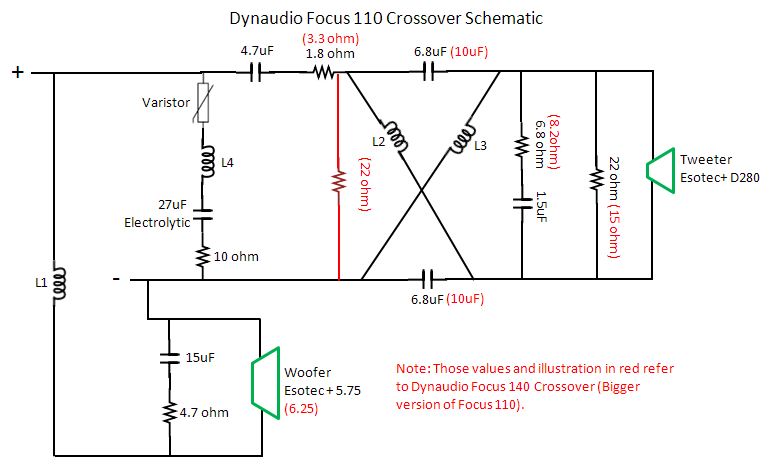
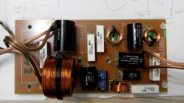
Good day, I know there are a lot of great talent here. So I would really appreciate your answers, feedbacks, and comments on the questions base on the attached Picture layout of both Dynaudio Focus 110 and 140 Crossover schematic.
Question:
1) Circuit of Varistor + L4 + 27uF + 10 ohm is a band pass or notch filter for the resonance frequency of the tweeter?
- I believe the varistor is the fail safe for the amp consider irregularity of electrolyte cap, is it correct?
- Consider the temperament of the electrolyte, what can we expect of the sound when dissipation factor is high or irregular?
- Can we perceive the midrange may have some harshness because of non linear behavior of the electrolyte?
2) Circuit 6.8ohm + 1.5uF is for the rising impedance of the tweeter in higher frequency?
- Sound wise, what can we perceive if we do not treat this rising impedance, considering the amp will not compensate?
- What is your opinion on the sound for well flatten rising impedance?
3) Can I consider the lattice filter of 2 pcs caps and 2pcs Inductors is theoretically to have no contribution to any additional resistance, capacitance, phase, or inductance to the tweeter + and -?
- Is the 10uF of the Focus 140 means a wider range of high frequency being subjected to this time delay? If not what is the increased capacitance do?
4) What is your opinion over the additional 22 ohm resistor(not in the Focus 110 crossover) in the crossover for Focus 140 over the Focus 110?
- Does it mean the Focus 140 trying to regulate 2 frequency peaks in the high frequency range after the 4.7uF 1st order cross?
- Is it better to flatten the impedance peak of Focus 140 using only 1 parallel resistor only instead of 2?
- Why do we need the additional 22 ohm resistor in the Focus 140 circuit?
Attachments

How do you know this is the schematic of said products?
There is still project data available for vintage Dynaudio DIY speakers
that employ almost the same filter solution with obviously different
part values.
Are you sure this is a varistor in series with RLC?
In general, your best way to learn what filter does in a circuit
is to simulate with a speaker.
RLC in parallel with amp out, flattens system impedance, does
not change FR. Resistors Rs and Rp define attenuation of tweeter.
What you call lattice and series cap shape response.
Nothing special and I would say unnecessary complicated.
This is impedance correction.Question:
1) Circuit of Varistor + L4 + 27uF + 10 ohm is a band pass or notch filter for the resonance frequency of the tweeter?
- I believe the varistor is the fail safe for the amp consider irregularity of electrolyte cap, is it correct?
- Consider the temperament of the electrolyte, what can we expect of the sound when dissipation factor is high or irregular?
- Can we perceive the midrange may have some harshness because of non linear behavior of the electrolyte?
The elco is not in series with the speakers and therefore has no audible influence on the sound.
The filter itself is a first order filter (L1 and the 4,7uF cap). If you perceive midrange hardness, that would be my suspect.
Its is indeed impedance correction. Its there so the filter can do what its supposed to do.2) Circuit 6.8ohm + 1.5uF is for the rising impedance of the tweeter in higher frequency?
- Sound wise, what can we perceive if we do not treat this rising impedance, considering the amp will not compensate?
- What is your opinion on the sound for well flatten rising impedance?
This is an allpass filter. It has a time delay effect.3) Can I consider the lattice filter of 2 pcs caps and 2pcs Inductors is theoretically to have no contribution to any additional resistance, capacitance, phase, or inductance to the tweeter + and -?
- Is the 10uF of the Focus 140 means a wider range of high frequency being subjected to this time delay? If not what is the increased capacitance do?
The speakers use different mid bass drivers, so the allpass filter needs to be different.
Its a voltage divider, making sure the outputs of both drivers is the same.4) What is your opinion over the additional 22 ohm resistor(not in the Focus 110 crossover) in the crossover for Focus 140 over the Focus 110?
- Does it mean the Focus 140 trying to regulate 2 frequency peaks in the high frequency range after the 4.7uF 1st order cross?
- Is it better to flatten the impedance peak of Focus 140 using only 1 parallel resistor only instead of 2?
- Why do we need the additional 22 ohm resistor in the Focus 140 circuit?
The filter itself is a first order filter (L1 and the 4,7uF cap).
If you perceive midrange hardness, that would be my suspect.
Hi,
the RC circuit in parallel with bassmid increases the steepness
of the LP filter and attenuates higher frequencies. There is no
midrange harshness with commercial Dynaudio products.
Hi,
the RC circuit in parallel with bassmid increases the steepness
of the LP filter and attenuates higher frequencies. There is no
midrange harshness with commercial Dynaudio products.
That RC circuit is impedance correction. It makes sure the filter can do what its supposed to do: Be a first order filter.
First order filters place a high strain on the tweeter witch could be audible? Just guessing here.
I have a very similar Dynaudio design (D28/2 and 17W75XL) and hear no midrange hardness.
Breaking down a complex crossover involves some modelling usually. I did something similar to a B&W Matrix 3:
http://www.diyaudio.com/forums/multi-way/236806-could-kind-soul-please-break-down-horrid-xover-10.html#post3520563
You have a well behaved 4 ohm (?) polycone bass with a simple ca. 1mH coil and Zobel. Only a few 5-6" woofers will respond to this simplicity, but Dynaudio and Morel are two examples that work.
That crisscross lattice tweeter filter is a standard sort of old group delay equaliser, but interestingly, a simple shunt coil does much the same thing. The filter is also found on the Zaph|Audio - ZD5 - Scan Speak 15W8530K00 and Vifa XT25
So what you have there is second order electrical filters at heart with RC driver impedance correction and some overall LCR crossover impedance correction. And some tweeter attenuation. The Zobel works with attenuation on the tweeter to increase the top-end rolloff. A good Dynaudio archive here:
Dynaudio archive
I would guess the overall acoustic filter is BW3.
So what you have there is second order electrical filters at heart
I see only a first order filter, but I can be wrong.
What are the parts that make up the second order filter?
I see only a first order filter, but I can be wrong.
What are the parts that make up the second order filter?
On the bass, the Zobel-type RC circuit adds the second order electrical element to the first order coil. It effectively damps the voicecoil too.
On the tweeter, the lattice filter adds an inductance to the first order capacitor.
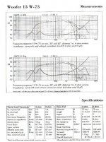
It's certainly not 6dB/octave overall rolloff. That would sound terrible. But really, it's the wrong way to look at it. You combine the electrical filter with the mechanical filter of the drivers to get something reasonable like 12-18dB/octave rolloff and do your thing with phase alignment, however it works out. The example 5" Dynaudio 15 W-75 has considerable internal damping and very low inductance. A unique sort of driver.
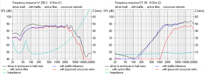
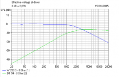
You can see how a second order bass/third order tweeter filter is best combined with natural rolloff below.
Attachments
On the bass, the Zobel-type RC circuit adds the second order electrical element to the first order coil. It effectively damps the voicecoil too.
On the tweeter, the lattice filter adds an inductance to the first order capacitor.
It's certainly not 6dB/octave overall rolloff. That would sound terrible. But really, it's the wrong way to look at it. You combine the electrical filter with the mechanical filter of the drivers to get something reasonable like 12-18dB/octave rolloff and do your thing with phase alignment, however it works out. The example 5" Dynaudio 15 W-75 has considerable internal damping and very low inductance. A unique sort of driver.
You can see how a second order bass/third order tweeter filter is best combined with natural rolloff below.
I understand what your saying, but I'm not convinced.
If I have time, witch atm I have not, I'll do some measurements and see what the electrical filters are.
I agree on the mechanical+electrical filters stuff.
Ew! You're quite right, Tattoo! 
I should have simmed it before speaking.
Looks like those filters ARE 6dB per octave electrically. Must be good drivers to get away with that! The Lattice part mostly corrects phase, as advertised.
I should have simmed it before speaking.
Looks like those filters ARE 6dB per octave electrically. Must be good drivers to get away with that! The Lattice part mostly corrects phase, as advertised.
Attachments
Hi Tattoo,
Question 4, voltage divider in this circuit looks like l pad attenuation? Why focus 140 has 2 of such resistors (22 and 15 ohm), while focus 110 only require 1?
It seems to me that the 15 and 22 Ohm resistors are parallel, making a +-9 Ohm resistor. Its not close enough to a E12 series resistor.
Ew! You're quite right, Tattoo!
I should have simmed it before speaking.
Looks like those filters ARE 6dB per octave electrically. Must be good drivers to get away with that! The Lattice part mostly corrects phase, as advertised.
Can't believe I'm actually right.
So I suppose, after that digression we are back to the original circuit!
The varistor is mysterious. It might be there to compensate some thermal effects. I wouldn't have thought the electrolytic would have many issues though. It's only impedance correction.
A bit of varied attenuation on the tweeter filter with different efficiency and response woofers is not surprising.
AFAIK, the 5.75" driver must be the Dynaudio Esotec MW 152 which naturally rolls off at 3kHz. The Zobel is about right for 3R and Le 0.24mH.
Impedance Equalization (L-Pad) Circuit Designer / Calculator
The lattice DOES affect phase. That's what it's there for.
Looks like Dynaudio tend to a 12dB/octave 2nd order tweeter filter on car audio. If there's an issue with the above 1st. order, it would be tweeter harshness IMO. The woofer should sound OK at 6dB octave.
I doubt its a varistor
If it was, then the impedance correction wouldn't work.
Varistor's have high impedance with low voltages across them and low impedance with high voltages across them.
110 impedance:
From here: SoundStage! Measurements - Dynaudio Focus 110 Loudspeakers (12/2006)
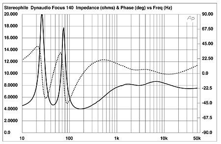
Dynaudio Focus 140 loudspeaker Measurements | Stereophile.com
These speakers measure very very good.
If it was, then the impedance correction wouldn't work.
Varistor's have high impedance with low voltages across them and low impedance with high voltages across them.
110 impedance:
From here: SoundStage! Measurements - Dynaudio Focus 110 Loudspeakers (12/2006)
Dynaudio Focus 140 loudspeaker Measurements | Stereophile.com
An externally hosted image should be here but it was not working when we last tested it.
These speakers measure very very good.
On the bass, the Zobel-type RC circuit adds the second order electrical element to the first order coil. It effectively damps the voicecoil too.
On the tweeter, the lattice filter adds an inductance to the first order capacitor.
It's certainly not 6dB/octave overall rolloff. That would sound terrible. But really, it's the wrong way to look at it. You combine the electrical filter with the mechanical filter of the drivers to get something reasonable like 12-18dB/octave rolloff and do your thing with phase alignment, however it works out. The example 5" Dynaudio 15 W-75 has considerable internal damping and very low inductance. A unique sort of driver.
You can see how a second order bass/third order tweeter filter is best combined with natural rolloff below.
A Zobel, done correctly, is the complex conjugate of the load making the overall input look resistive around the crossover point. The bass inductor into the resistive load is first order not second. It is possible to adjust the values in order to shape the roll-off but still it would be roughly first order. True you do have to cascade the driver response but it is probably quasi first order over part of the roll-off band.
Similarly the 4.7 cap to the tweeter is first order, and again you have to also consider the acoustical response but for part of the band it will be first order.
Last edited:
Hi System 7,
Thanks for the new inputs to prove it is 1st order crossover, which is what Dynaudio said back in 2006 when Focus 110 and 140 launched. - In the lattice filter, the difference between 6.8uF and 10uF of the Focus 140 means a wider range of high frequency being subjected to this time delay? If not what is the increased capacitance do?
Hi Tattoo,
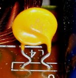
Thanks for the feedback and doubt. Attached are the details of the of the varistor, or should I call it resettable fuse? If you may:
- I believe the varistor is the fail safe for the amp consider irregularity of electrolyte cap, is it correct?
- Consider the temperament of the electrolyte, what can we expect of the sound when dissipation factor is high or irregular?
- Can we perceive the midrange may have some harshness because of non linear behavior of the electrolyte?
HI Guys,
Correct me if I am wrong: Circuit of Varistor + L4 + 27uF + 10 ohm is a band pass filter. It is to deal with the resonance frequency of the tweeter. From what I can find, fs=1300Hz.
From the various sources in the internet over the Focus 110 Frequency Response graph, you can see a surge of around 5dB from 5kHz to 7kHz. This region should very much exaggerate the sibilance in a vocal track. But the off axis measurement of 15 to 30 degree has somehow flatten this peak. In Asian country majority of our houses are of concrete and tile, which make this quite audible. So I need to know the sibilance has something to do with band pass filter, since electrolyte cap is a bit non-linear around the audible range of frequency?
I am sorry I post these questions as I dont have the luxury of measurement toys or other tools to verify it. Neither that I know how to use it correctly if I have one Changing components in and out of the speakers to find out what are and what arent will most likely wear off the screw holes or causing more handling damage.
So I would like to get you guys which have great experience to make some eudcated guess into how it may sound when something is changed. This I believe it is the harder part of crossover know how than the already explained LCR network can do electrically.
Thanks for the new inputs to prove it is 1st order crossover, which is what Dynaudio said back in 2006 when Focus 110 and 140 launched. - In the lattice filter, the difference between 6.8uF and 10uF of the Focus 140 means a wider range of high frequency being subjected to this time delay? If not what is the increased capacitance do?
Hi Tattoo,
Thanks for the feedback and doubt. Attached are the details of the of the varistor, or should I call it resettable fuse? If you may:
- I believe the varistor is the fail safe for the amp consider irregularity of electrolyte cap, is it correct?
- Consider the temperament of the electrolyte, what can we expect of the sound when dissipation factor is high or irregular?
- Can we perceive the midrange may have some harshness because of non linear behavior of the electrolyte?
HI Guys,
Correct me if I am wrong: Circuit of Varistor + L4 + 27uF + 10 ohm is a band pass filter. It is to deal with the resonance frequency of the tweeter. From what I can find, fs=1300Hz.
From the various sources in the internet over the Focus 110 Frequency Response graph, you can see a surge of around 5dB from 5kHz to 7kHz. This region should very much exaggerate the sibilance in a vocal track. But the off axis measurement of 15 to 30 degree has somehow flatten this peak. In Asian country majority of our houses are of concrete and tile, which make this quite audible. So I need to know the sibilance has something to do with band pass filter, since electrolyte cap is a bit non-linear around the audible range of frequency?
I am sorry I post these questions as I dont have the luxury of measurement toys or other tools to verify it. Neither that I know how to use it correctly if I have one
Changing components in and out of the speakers to find out what are and what arent will most likely wear off the screw holes or causing more handling damage.So I would like to get you guys which have great experience to make some eudcated guess into how it may sound when something is changed. This I believe it is the harder part of crossover know how than the already explained LCR network can do electrically.
Attachments
- Home
- Loudspeakers
- Multi-Way
- Dynaudio Focus 110 and 140 Crossover Comparison Details