It looks to me like the 27uF is not a critical component based on a huge amount of coil guessing! A 33uF in the LCR made little difference.
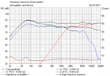
It is a 6dB/octave filter. The actual Dynaudio basses are wildly more rolled off than the ones I used, but the electrical sim and impedance can still be trusted IMO. Amazing big voicecoil on the bass! And we know the tweeter has huge 3mm xMax to cope with low frequencies, if you like that sort of thing.
The dotted line in the impedance response shows the LCR impedance correction is actually almost unnecessary. It's quite well-behaved anyway.
I don't know why you are changing the caps at all, TBH.
I would be examining fitting a higher order tweeter filter. Which is really going to change things. No pussyfooting about!
Oh, drat, I think I wired the basses wrong!
I´m going to replace the capacitors because according to this web, and many forums, the sound will be better:
Humble Homemade Hifi - Cap Test
Am I missing something ?
Could someone enlighten me as to how that network interacts with the drive units when as drawn it appears to be just an additional load to the amplifier that serves no purpose.
You mean the network is designed to 'interact' with the unknown (and probably fairly high and variable) output impedance of a valve amp. To follow on from that then I would say that for solid state amps it would be better removed.
So the questions to be asked should really be what amplifiers are being used with these and also what speaker cable and what length.
OK, I'll not drag the debate out. Carry on
So the questions to be asked should really be what amplifiers are being used with these and also what speaker cable and what length.
OK, I'll not drag the debate out. Carry on
I finally upgrade the solens to clarity cap CSA (dynaudio audience 52 SE)and only in one speaker.
The result: The sound is exactly the same . I put the speakers together and change the balance with the pc. No differences can be heard.
The result: The sound is exactly the same
. I put the speakers together and change the balance with the pc. No differences can be heard.Attachments
Well, I did tell you I thought upgrading caps from Solen MKP to Clarity Cap MKP was a waste of time! I don't know why people say the difference is night and day. My own theory is they just unplug and then replug everything, so get a better fresh metal connection. Which is good on all audio connectors.
There is some evidence that thicker foils (lower resistance) might help a capacitor at bass frequencies, and audio capacitors probably don't have great radio frequency characteristics. But these are circumstances you usually don't encounter.
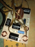
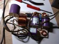
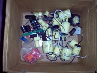
I have a box of capacitors including 50V NP Electrolytics, MKT and 250V Solen and 630V Mains rated MKP. TBH, the yellow high voltage ones are a pain. Being huge! The smaller black ones are 250V Solens. I can never hear the difference beyond NP being a slightly different animal to use, because you allow for the 0.5-1R ESR. There are ways of making low inductance capacitors, involving them being 4X the size IIRC. But inductance is usually negligable with capacitors and wirewound resistors.
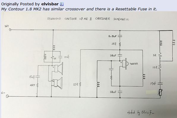
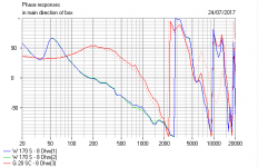
I can explain what the above tweeter lattice network does. It's not impedance shaping, which is done by the network on the right. It's a delay line. We used to call them group delay equalisers. In a loudspeaker, they effectively recess the tweeter, here about 30mm. They were useful in analog telecoms precisely because they didn't wreck impedance. A LC network is to some extent a lumped parameter version of a long delaying cable with a certain impedance. The impedance is Root (L/C), so should be near 6 ohms with a slight complexity in having two of them.
Applying a lattice, which includes a polarity flip, ends up in much the same place as a 30mm tweeter recess, done with a stepped baffle or a sloped one. It time-aligns the flat baffle tweeter in effect. I show the lattice network effect as dotted, versus the solid time alignment (and polarity flip) without it of 30mm recess below.
snip...
I don't know why you are changing the caps at all, TBH.
I would be examining fitting a higher order tweeter filter. Which is really going to change things. No pussyfooting about!
There is some evidence that thicker foils (lower resistance) might help a capacitor at bass frequencies, and audio capacitors probably don't have great radio frequency characteristics. But these are circumstances you usually don't encounter.
I have a box of capacitors including 50V NP Electrolytics, MKT and 250V Solen and 630V Mains rated MKP. TBH, the yellow high voltage ones are a pain. Being huge! The smaller black ones are 250V Solens. I can never hear the difference beyond NP being a slightly different animal to use, because you allow for the 0.5-1R ESR. There are ways of making low inductance capacitors, involving them being 4X the size IIRC. But inductance is usually negligable with capacitors and wirewound resistors.
I can explain what the above tweeter lattice network does. It's not impedance shaping, which is done by the network on the right. It's a delay line. We used to call them group delay equalisers. In a loudspeaker, they effectively recess the tweeter, here about 30mm. They were useful in analog telecoms precisely because they didn't wreck impedance. A LC network is to some extent a lumped parameter version of a long delaying cable with a certain impedance. The impedance is Root (L/C), so should be near 6 ohms with a slight complexity in having two of them.
Applying a lattice, which includes a polarity flip, ends up in much the same place as a 30mm tweeter recess, done with a stepped baffle or a sloped one. It time-aligns the flat baffle tweeter in effect. I show the lattice network effect as dotted, versus the solid time alignment (and polarity flip) without it of 30mm recess below.
Attachments
Last edited:
I know this is an old thread, but I am about to up-spec some F110s and I came across this thread in the process. I have already successfully done several pairs of F220s, and several other series of Dynaudio speakers. The 1st generation Focus series have an all-pass network in series with the tweeter to time align the acoustic centre of the tweeter with the bass driver. The crossover networks have Zobel impedance compensation for the drivers so that the filters are terminated by simple resistive impedances, otherwise the filter slopes would not be correct. The Zoble networks do not make the crossovers second order, and both low pass and high pass are essentially first order acoustic (i.e. voltage and speaker frequency response combined). The bandpass at the input to the crossover is impedance correction for the whole system so that the amplifier sees a benign load right up to RF. A perfect amplifier is a voltage source, but real amplifiers are not perfect and work best into a non-reactive load! The PTC device in series with the bandpass is to prevent it being destroyed by a clipping amplifier.
There are four simple steps, which when combined, make an substantial improvement to sound quality from all the Focus series, bringing them up to or surpassing the quality of the equivalent Contour model. Changing the crossover slopes, topology, or capacitors is generally not necessary (except for DM Center and Excite Centre - see below).
1. Reduce the series resistance of the lowpass inductor. Halving the series R will reduce upper bass driver colouration by 6dB, and will increase output level fo the bass driver(s) by 1dB. Use an air-core inductor. The improvement from reducing series R is much greater than that from any esoteric winding technique or unobtainium material used in the construction of the inductor.
2. Reduce the series resistance of the all-pass inductors. This is necessary to bring up the output of the tweeter to match the bass driver(s) with low R coil. Here you can use a toroidal inductor to save cost as the cores will not saturate with the little energy and high frequencies in this part of the circuit.
3. Damp the rear chamber of the tweeter. If you tap the back of the tweeter with a pencil it sounds like a coconut shell. This resonance is excited by any transient signals and is clearly audible out of the front of the tweeter. Fill and cover the tweeter plastic back with "bluetack" or better sound deadening material.
4. With the drivers out of the cabinets, tap the sides, front and back of the cabinets. You will find some areas that are very resonant. Adhere additional damping sheets over these panels to make the cabinet 'dead' everywhere.
These steps work equally well for other Dynaudio model ranges, particularly the Audience and DM series.
Note: Most, but not all vintage Dynaudio speakers have first order crossovers. First order crossovers preserve the power response of the audio input signal with two significant benefits: A. the room will sound better (the speaker is more 'room tolerant'); and B. speech and timbre have greater clarity, which is a function of both room response (see A.) and the physiology of human hearing. This is a property of first order crossovers - no second or higher order crossover can recombine with the original power response, regardless of filter design, or whether the filter is passive or active, analogue or digital - it's just physics/mathematics.
Changing the DM and Excite centre speakers back to a first order topology whilst applying the above steps 1, 3 & 4 (no all-pass on the lower model ranges) makes them hugely better for the task of a centre channel speaker.
In general, the above principles apply to all loudspeakers, but their may be other considerations that are more important for any particular design. Changing crossover order is not a trivial task because the resultant system output is a function of the drivers' acoustic responses, baffle loading, interaction between driver impedance characteristic and filter design. This is a major undertaking and generally unnecessary with vintage Dynaudio designs (i.e. designs that predate the sale of Dynaudio to GoerTek (China) in late 2014).
@johnmath, I'm quite interested in your recommendations as I have circa-2015 F260s. I love the silky highs from the Esotar2 tweeters, and the superb overall coherence. However, I've been wondering if there was a way to eliminate the midbass coloration, without messing with the low-order and phase coherent aspects of the existing design.
I just came across your post while searching for ideas regarding the above, and your recommended steps look to be exactly what the doctor ordered!
My skills are on the basic side, so some questions on steps 1 & 2...
As I don't yet have the F260 schematic worked out yet, I'll refer to the F110/F140 schematic that's posted earlier in this thread as a rough analogue.
1) I understand that I should remove the low-pass inductor L1 or equivalent. Then measure and replace with a suitable air conductor inductor with half the series resistance of the original.
Questions: What are the recommended ways to do the measurement? Would a decent quality LCR meter suffice?
2) I understand that I should remove the all-pass inductors L2 and L3 or equivalents. Then measure and replace with suitable reduced series resistance inductors.
Questions: How do I determine the ideal series resistance? Is there a static measurement approach like with step 1? If not, do you have a sense of what % reduction would be a good starting point from your experience with F220s?
Thanks very much!
@johnmath or others. I would like to receive some help with my Dynaudio Focus 110. I have been irritated by the coloration of these speakers for a long time. The tweeters are good, but the woofer colors enormously in the middle and upper area. The loudspeaker is certainly not "focus" and transparent as claimed.
My skills are limited, however, I can solder well and can read the electro diagrams a little bit.
My dealer is not a fan of Dynaudio and says that there is too much resistance in the XO. This would be correct with John's adjustments. I would also like to his mods on this speakers before I give up the hope. But I do not know if i'm applying the mods right. I have enclosed the diagram. Perhaps John or someone else can advise with this. I would like to bring back the coloring and make the speaker more neutral and transparent. If possible
Attachments
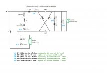
Sorry Arnold, did not see this post until now. Midrange colouration will be in the bass driver. The cause will be series resistance in L1, the bass driver low pass inductor, and the 15uF electrolytic capacitor in the Zobel network across the bass driver.
Replace L1 with an air core inductor of the lowest series resistance you can physically fit and afford, or a P-core which will be much smaller, cheaper and a good compromise.
Replace the electrolytic with a 15uF film capacitor. It doesn't have to be super expensive, an entry level Dayton, Solen or Crosscap will be perfect.
I can't find my notes on F110 so I'll have to open mine up and see what I did, what other changes I made and the alteration to the tweeter attenuation to match the increased output from the bass driver.
1) I understand that I should remove the low-pass inductor L1 or equivalent. Then measure and replace with a suitable air conductor inductor with half the series resistance of the original.
Questions: What are the recommended ways to do the measurement? Would a decent quality LCR meter suffice?
2) I understand that I should remove the all-pass inductors L2 and L3 or equivalents. Then measure and replace with suitable reduced series resistance inductors.
Questions: How do I determine the ideal series resistance? Is there a static measurement approach like with step 1? If not, do you have a sense of what % reduction would be a good starting point from your experience with F220s?
Sorry Stephen I didn't see your post until now.
The bass inductor should be replaced with an air-core 1.5mH with series resistance less than 0.2 ohms. The series resistance is always specified with good quality components and can be measured with a good quality LCR meter in the R range. The meter and clip leads will need to be calibrated before measuring; many digital LCR meters have a self-calibration mode.
I no longer change the all pass inductors as their series resistance is not an issue sonically. Instead, to bring up the tweeter output I change the attenuator resistors. I'll have to check what I've done and post back. It's also worth to change the 27uf electrolytic in the bass driver Zobel network with an audio grade film capacitor.
Apparently, great care has been taken with the crossover design of these two speakers. It’s nice to see a confirmation that Dynaudio was once a decent company, but my personal experience with their more recent products is not that good. In fact, it was exactly because of them that I decided to move to DIY and I would probably never buy commercial speakers ever again. At least not Dyns, that’s for sure. However, don’t want to go off topic. I just wanted to say that a lot of fans and owners of Dynaudio speakers think Focus is very good series especially for its price. Many believe the Focus line was scrapped on purpose because it was too successful for its price and competing with much more expensive models from the company.
but my personal experience with their more recent products is not that good
My experience with DM/Emit series was really great. It's the best speakers in its price range. It is almost impossible to make better with the same money
My experience with DM/Emit series was really great. It's the best speakers in its price range. It is almost impossible to make better with the same money
Well, I guess it’s all about taste, personal preferences and financial capabilities. I used to have Emit M10 and M20 and tried really hard to like them, but to no avail. For exactly the same price as Emit M20, one could get Focal Chorus 706 (now discontinued). I happened to compare them and the latter are way better in absolutely every department you can think of: excellent build quality with 20 mm thick MDF, non parallel side walls, internal bracing, double flared ports and, on top of that, they even measure better than the Dynes. Unfortunately, both companies use cheap components in their filters, but the crossover design of the Chorus 706 is just excellent with perfect phase tracking, for instance.
I have many other issues with Dynaudio, but it’s a topic for another thread...
they even measure better than the Dynes
Not even close to Dynaudio
. Emit M20 has very neutral and flat response.build quality with 20 mm thick MDF

Dynaudio is thicker
Last edited:
Sorry Stephen I didn't see your post until now.
The bass inductor should be replaced with an air-core 1.5mH with series resistance less than 0.2 ohms. The series resistance is always specified with good quality components and can be measured with a good quality LCR meter in the R range. The meter and clip leads will need to be calibrated before measuring; many digital LCR meters have a self-calibration mode.
I no longer change the all pass inductors as their series resistance is not an issue sonically. Instead, to bring up the tweeter output I change the attenuator resistors. I'll have to check what I've done and post back. It's also worth to change the 27uf electrolytic in the bass driver Zobel network with an audio grade film capacitor.
@johnmath, we need to work on your response time.
j/k! I really appreciate your reply & expertise!
In the end, I decided to try some room treatments before wielding the scalpel (err, soldering iron).
I added tube traps in the corners behind the F260s (I scored a 3rd one and placed it behind and centered, for imaging improvements. Though that one was not really necessary).
And I pulled the F260s out a bit further into the room.
Then the icing on the cake was a preamp upgrade. It turns out the one that I was using previously was a bit too exhuberent for the F260s in my room size (Naim NAC282 => NAC252).
The result was much better, and no longer gives my ears the impression of excessive mid-bass. Hence, I am no longer very motivated to do surgery on the F260s.
In hindsight, I suspect that my room size is marginally sufficient for the F260s (~13' x 20.5' x 8'). The room treatment, plus a better preamp match made them work in this room. In fact, they are now superb - esotar-smooth with coherence, dynamic impact and excellent 3d dimensionality. Woot!
But I'm still interested in any further updates on what you did to your F110s, just in case I change my mind some day, or pick up some other Dyns and decide to play with them.
Last edited:
Ha ha, I didn't get notifications of responses to my post and only came back on impulse (2 puns intended).
No individual piece of high quality audio equipment should add or subtract from the original audio experience, but nothing being perfect they all do. I like the older Dynaudio systems from late nineties to the mid 2010s or so because Wilfried Ehrenholz really knew what he was doing. Since he sold Dynaudio to Goertek the company has gained scores of new engineers and simultaneously lost decades of knowledge and experience.
I have a memory problem so if I don't document something I forget what I've done, which has happened in the case of the F110s. Because of my memory problem I inevitably work from first principles on each project. When I have the time I will pull apart the F110s and post what I did. BTW I upgraded the 110s after I worked on a pair of Audience 42s, which subsequently seriously outperformed the 110s! Ironically I picked up those 42s from a bin after they had been blown up at an Xmas party and had to recoil them.
Last edited:
Stephen, I popped open the Focus 110s today to see what I had done. I generally can’t fault Dynaudio crossover designs so all I did was the standard upgrades I do to Dynaudio loudspeakers of the Audience, DM and Focus series. For the Excite series I do change the crossover configuration back to traditional Dynaudio first order topology for its superior time domain response and in-room power response.
The bass driver low pass inductor was replaced with one that has a DCR of <1/20 of the DCR of the bass driver, which in this case is 3 ohms, so the target for the inductor is less than 0.15 ohms. The original is 0.41 ohms. I usually would use an air-cored inductor, but I doubt if the ones I used for my Focus 220s would fit through the opening of the F110 bass driver. I used a Jantzen P-core part number 000-5144 1.2mH / 0.14 ohms inductor.
Electrolytic capacitors should be replaced with audio grade film capacitors. It’s a misnomer to think capacitors in bypass locations don’t need to be audio grade; after all it is audio they are bypassing and if they fail to do that well it will be audible! I can’t remember if I replaced the capacitor in the bass driver Zobel network (R1 and the 15uF capacitor) but it has a Solen metalised polypropylene in there, the same as other capacitors Dynaudio have used.
I didn’t change the 27uF electrolytic because when I did these years ago. I mistakenly thought it was an out of band equalisation network to make the load impedance seen by an amplifier benign above 20kHz. It isn’t; it’s a frequency shaping network so it needs to be changed and I have ordered Dayton DMPC polypropylene capacitors for that (they’re a little smaller and it’s a tight fit).
The tweeter rear chamber is resonant at ~2kHz and needs damping, so I plugged the dimple and covered the rear with a stick-on constrained damping material, like that used in cars behind speakers. Leave the tiny vent hole in the back uncovered so the tweeter diaphragm can adjust to changes in barometric pressure.
I don’t change the other small inductors in the tweeter circuit as their series resistance is already factored into the crossover tuning and to change them would upset it.
In the larger cabinets it is beneficial to add damping to any resonant areas of the cabinet, but there’s not much untreated cabinet wall surface left to damp in these little boxes, so I didn’t add any.
Nor did I upgrade the internal wiring as it is quite substantial anyway. For the F220s I replaced the internal wiring with Canare 4S11 (for input) and 4S8 (for drivers) star-quad speaker cable wired for inductance cancelling, as this prevents the leads becoming loosely coupled transformers with each other or anything else, and significantly reduces any microphonic contribution from the cables.
Now that I think about it, when the capacitors arrive, I will replace the woofer and tweeter leads with Canare 4S8.
The final tuning that Dynaudios benefit from is seriously good leads to the amplifier, and good amplification. My preference is Canare 4S11 for leads up to 4 metres or so. That gives 4mm2 of oxygen free long crystal copper per side, PE insulated in a mechanically constrained construction. Properly wired in star-quad configuration it has minimal external magnetic field, and low microphonic interaction. And it’s not expensive, but hard to beat.
- Home
- Loudspeakers
- Multi-Way
- Dynaudio Focus 110 and 140 Crossover Comparison Details