Hi system7, thanks for the simulation and new approach. Not ready to do such drastic change.
But generally, the 10uf of focus 140 lattice filter is meant for wider range of frequency delay or longer delay time?
A drastic simplification, I would say! I wonder what the point of this thread is if you aren't planning some change too.
")
Let's reiterate. With a transistor amp, the LCR impedance correction can be dispensed with. The lattice can go too, since a higher order filter has more group delay too.
The function of the lattice filter is to compensate for time alignment issues. One of the first circuits I ever built in the lab when we had to meet a Post Office Telephone group delay specification on an audio circuit in telecoms, as it goes. It trades some frequency response and impedance ripple for group delay correction. It's a bit like adding a long length of cable to a circuit in effect.
Or correcting the time alignment physically:
Ellam-Discovery-15
So yes, off the top of my head, 10uF will do more with those unknown coils, whatever they might be.
Hi system7, kind of like preserve some of the characteristic of the speaker. So not so much change.
Ultimately, i am trying to understand as much as i can of both speakers crossover. It seem the focus 110 is meant for nearfield and a bit more peaky overall sound; trade off smoothness. While the focus 140 is made for a more even hand approach to sound, a flatter FR.
Both speakers r very similar in crossover layout. I am interested to find out how focus 140 manage it. It is obviously focus 140 has a greater l pad attenuation. But not sure why 2 parallel resistor instead of 1?
Also no certain answer as to why resettable fuse is not meant for possible electrolyte malfunction. As i am interested to bypass this fuse, but a very dangerous thing to do if the cap isnt upgrade to pp. while even more uncertain when tattoo describe it to be like a precondition circuit.
Rest assure the actual crossover has been attenuated and with a better quality cap in series. I am interest to know more of the circuit. In theory all the impedance correction has no relation to sound. Just like saying red is red and nothing else, no shading whatsoever. If thing can be this simple
It seem the focus 110 is meant for nearfield and a bit more peaky overall sound; trade off smoothness.
It could be that you're hearing a peak in the upper midrange response of the 5.75" Dynaudio woofer: Dynaudio 15W75-
"The 15W75-04 is a particular “troublesome” driver as it has two intrinsic resonances that have to be taken care of in the crossover design."
The Soundstage review shows a similar 2300Hz peak in the Focus 110 on-axis and off-axis response, possibly causing the speaker to sound a bit bright or forward in a lively room.
While the focus 140 is made for a more even hand approach to sound, a flatter FR.
The 7" Dynaudio woofer appears to have a much smoother upper midrange response.
Hi Lojzek, any reason why it want to do that?
The reasons why this particular circuit can or can't do
something, has to do with law of physics and manufacturer's
vision od good design for this particular product.
Get yourself a good electronics book, study the matter,
use simulation software and you will eventually find
all the answers to questions bugging you.
Here is the tweeter spec:
http://www.gattiweb.com/images/dynaudio/esotec-d260_data.pdf
Nice web site here but it does not seem to have the Esotec 5.75 data sheet.
If you had FRD and ZMA files for these we could simulate it in Xsim - anyone have them?
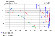
Dynaudio has always been in the 1st order crossover camp with as I recall claims for
linear phase. It would be interesting to check for this in simulation. Xsim has options
to look at Impulse, Step and square wave response.
http://www.gattiweb.com/images/dynaudio/esotec-d260_data.pdf
Nice web site here but it does not seem to have the Esotec 5.75 data sheet.
If you had FRD and ZMA files for these we could simulate it in Xsim - anyone have them?
Dynaudio has always been in the 1st order crossover camp with as I recall claims for
linear phase. It would be interesting to check for this in simulation. Xsim has options
to look at Impulse, Step and square wave response.
Last edited:
Dynaudio has always been in the 1st order crossover
camp with as I recall claims for linear phase.
So they claimed. Opened up an Audience speaker,
1st order on bassmid, 2nd on tweeter. No complications
like Focus.
Hi PB2,
Thanks. It should be D280, as advertised by Dynaudio, in their own website. But the data is close enough. I always thought D260 is with 26mm dome diameter, it is not!
Do you have links to the driver specs, or are they not published?
Still need FRD/ZMA files to do an accurate simulation.
Hi PB2,
There is no Driver specs for these guys when Dynaudio decided to pull out from the DIY market.
So I suspect this is the closest: http://www.gattiweb.com/images/dynaudio/d28-2_data.pdf
There is no Driver specs for these guys when Dynaudio decided to pull out from the DIY market.
So I suspect this is the closest: http://www.gattiweb.com/images/dynaudio/d28-2_data.pdf
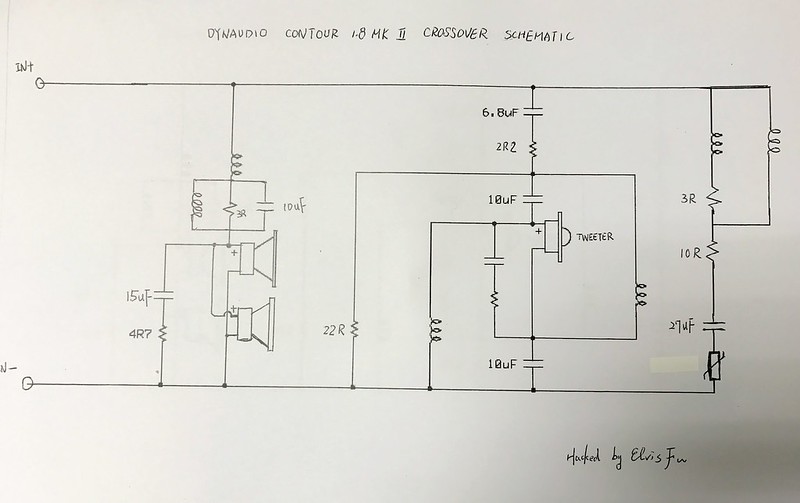
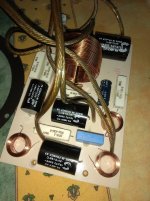
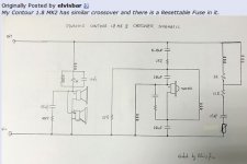
My Contour 1.8 MK2 has similar crossover and there is a Resettable Fuse in it.
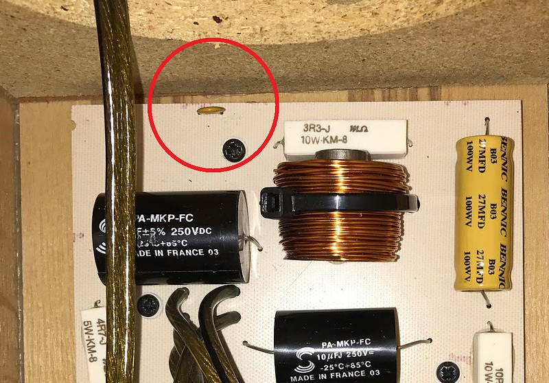
Excuse me, can you help me? I´m planning to upgrade my audience 52 SE (bought in 2004) crossover capacitors with clarity cap CSA.
The question is about the 27 uf bennic electrolytic capacitor (I think it is the bennic b10 model), wich I can also see in your focus scheme. What it does?
The problem is that I can´t find a 27 uf cap, most are 22 or 33 uf. Is there any problem if i use 33uF 70V Mundorf ECap AC bipolar PLAIN electrolytic capacitor? Or it´s better to leave it as it is? Thanks
More info here: Mundorf ECap AC Bipolar Capacitors | Hifi Collective
Attachments
Last edited:
You can use a 2uF and 4.7uF in parallel to get close to 27uF.
Take a look at this image.https://sub.allaboutcircuits.com/images/00299.png
Take a look at this image.https://sub.allaboutcircuits.com/images/00299.png
You mean parallel 22uF and 4.7uF for 27uF total, of course.
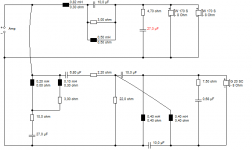
I'm getting a headache just looking at that one. It's the old delaying lattice again, isn't it? It is a shallow 6dB filter electrically AFAIK. The Dyanaudio tweeters seem to have an extraordinary Xmax around 3mm (long tinsel leads?) so they seem to survive this.
I'm getting a headache just looking at that one. It's the old delaying lattice again, isn't it? It is a shallow 6dB filter electrically AFAIK. The Dyanaudio tweeters seem to have an extraordinary Xmax around 3mm (long tinsel leads?) so they seem to survive this.
Attachments
You mean parallel 22uF and 4.7uF for 27uF total, of course.
I'm getting a headache just looking at that one. It's the old delaying lattice again, isn't it? It is a shallow 6dB filter electrically AFAIK. The Dyanaudio tweeters seem to have an extraordinary Xmax around 3mm (long tinsel leads?) so they seem to survive this.
But what happen if i put only the 33 uf one that i have already bought?
Last edited:
Reading back over the thread and there seems to be question mark over whether the circuit is even drawn correctly.
If it is as drawn, and assuming the whole network is fed from a voltage source (i.e. low output impedance amp) then the network does nothing beyond adding an extra load to the amp.
Am I missing something ?
I would suggest that no one would be any the wiser.
If it is as drawn, and assuming the whole network is fed from a voltage source (i.e. low output impedance amp) then the network does nothing beyond adding an extra load to the amp.
Am I missing something ?
But what happen if i put only the 33 uf one that i have already bought?
I would suggest that no one would be any the wiser.
I don't know if you'd hear it either, but the 27uF is part of an LCR impedance correction circuit. A 33uF would give you a different Q and centre frequency. So I'd guess you'll have a little ripple in the impedance.But what happen if i put only the 33 uf one that i have already bought?
Since the NP electrolytic is in series with 10R, it's hardly stressed and ESR shouldn't play much part. But in general resonant circuits are most demanding of tolerances and quality.
Sorry, I'm too lazy to sim this one. But you should.
Downloads
I don't know if you'd hear it either, but the 27uF is part of an LCR impedance correction circuit. A 33uF would give you a different Q and centre frequency. So I'd guess you'll have a little ripple in the impedance.
Since the NP electrolytic is in series with 10R, it's hardly stressed and ESR shouldn't play much part. But in general resonant circuits are most demanding of tolerances and quality.
Sorry, I'm too lazy to sim this one. But you should.
Downloads
I don´t know too much about electronics so...
I think i´m going to leave the electrolytic, or in any case use the 22+4.7 in parallel as you suggested before.
For the moment i´m going to replace the solens with clarity cap CSA of the same value and voltage.
Thanks system7
Last edited:
It looks to me like the 27uF is not a critical component based on a huge amount of coil guessing! A 33uF in the LCR made little difference.
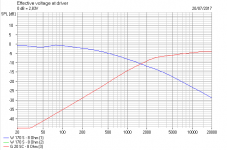
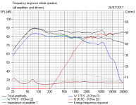
It is a 6dB/octave filter. The actual Dynaudio basses are wildly more rolled off than the ones I used, but the electrical sim and impedance can still be trusted IMO. Amazing big voicecoil on the bass! And we know the tweeter has huge 3mm xMax to cope with low frequencies, if you like that sort of thing.
The dotted line in the impedance response shows the LCR impedance correction is actually almost unnecessary. It's quite well-behaved anyway.
I don't know why you are changing the caps at all, TBH.
I would be examining fitting a higher order tweeter filter. Which is really going to change things. No pussyfooting about!
Attachments
Last edited:
- Home
- Loudspeakers
- Multi-Way
- Dynaudio Focus 110 and 140 Crossover Comparison Details