


Technically it's called a 2.5 way speaker.
I see from the pics of the speakers that both the woofer and the midrange work in tuned reflex enclosures. The woofer volume is double than the one where the midrange is housed.
Also the position makes some sense...As the woofer is on the bottom and the mid at the top, so they can "make noise" without interfering with themselves; the highpass cap on the midrange is omitted due to its capacity ( bad name in this case....!?! ) to stand the lower notes without distorting.
The separated paths crossover circuit would work best with an amplifier driving the speaker directly.
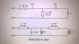
Thanks for the reply. Did you notice, in the original B&W schematic, that the mid range has a 0.9mH coil and the bass has 5.0mH coil. In my schematic of the mod I kept a 0.9mH coil going to the mid and a 5.9mH going to the bass. My reasoning was that I thought maybe the 0.9mH and 5.0mH were additive in the original B&W schematic Is that a right or wrong assumption?
Thanks,
henrylrjr
Thanks,
henrylrjr
Dear henrylrjr, I’m afraid neither woofer will work as intended in your schematic. You can’t separate this crossover like that. The midbass (0.9mH) will be close (not exactly the same though), the bass would need about 9mH for a somewhat similar slope (similar in the general slope, but with differences regarding the initial/later slope characteristics). You can’t separate them like that, since in the original crossover each driver is a crossover component regarding the circuit that the other driver is driven by.
Of course they add ... Though I didn't notice that
One thing to speculate: the driver might be represented as a complex R-C-L
circuit; when they are in the same circuitation, such as a parallel (paths) X-over for the two drivers in a 2.5 way system, they inter-act ( Maxwell & Thevenin ) with themselves and with the passive components and the acoustic load. Once they are divided the things change.
Or not ? Using the same generator ( amplifier ) Hmmm, maybe damping factor and ...dunno ?!
Edit : What Thalis said
Though I didn't notice thatOne thing to speculate: the driver might be represented as a complex R-C-L
circuit; when they are in the same circuitation, such as a parallel (paths) X-over for the two drivers in a 2.5 way system, they inter-act ( Maxwell & Thevenin
) with themselves and with the passive components and the acoustic load. Once they are divided the things change.Or not ? Using the same generator ( amplifier )
Hmmm, maybe damping factor and ...dunno ?!Edit : What Thalis said
Thanks for all the replies. Does anyone know how I could convert this 2.5 way to a 3 way. This is the first time I've seen a mid without any caps or resistors. Don't get me wrong I don't think a lot of components are necessarily better. I would just like to squeak out a little more performance from these B&W P6s. They sound pretty good but I feel the xover is the weak link. Whatever I end up with for an xover design it will be in it's own outboard enclosure.
Thanks,
henrylrjr
Thanks,
henrylrjr
Well, I said <technically it's a 2.5 way speaker> but usually the 2.5 uses same mid-woofer, also for aesthetics; moreover, the bass outputs sums and give a +6dB . In this case I see this ( kevlar ? ) midrange which is in duty from many years, so it must be a good driver.
So it must be seen as a 3 way design; the woofer placed near the floor suggest a reinforcement due to reflection + sum ( again !) of about 3 dB.
Don't think that the electrical side needs upgrading when you don't see the project as a whole ( holistic approach).
The "open" midrange, not High Passed, passes most of the signal and it (might be ) is felt more lively - no lower harmonics truncated .
Try experimenting with double stereo amplifiers and passive line level crossovers to give the system a twist: a little increase in dynamics...
Otherwise you should mimic the different housing of the mid driver like in other models and re-think all the efficiencies and structure of the thing.
I'm thinking that I will duplicate the original xovers using very good components. The xovers in the speakers are cheap electrolytic caps, some iron core inductors and cheap resistors and there aren't many, so cost to upgrade parts will not be very high. I plan to put the new components in two small wooden boxes that will be mounted on the wall behind each speaker. Any thoughts on that plan would be appreciated.
I'm not familiar with passive line level crossovers but are they placed between the amp and preamp? Please let me know where, in a system, they are usually placed?
Thanks,
henrylrjr
I'm not familiar with passive line level crossovers but are they placed between the amp and preamp? Please let me know where, in a system, they are usually placed?
Thanks,
henrylrjr
I can't say I've given this a lot of thought, but what usually annoys about a mid driven by a mere coil is cone-breakup above 3kHz. Probably upgrading the crossover components won't do much.
Often fitting a bit of Zobel impedance correction can help. So after the 0.9mH coil, you fit a 10W wirewound 7.5R plus 8uF polypropylene capacitor shunt. That's for an 8 ohm nominal Kevlar driver here.
That will roll off the driver faster. Worth a try. Pure guesswork, but nothing will break.
Often fitting a bit of Zobel impedance correction can help. So after the 0.9mH coil, you fit a 10W wirewound 7.5R plus 8uF polypropylene capacitor shunt. That's for an 8 ohm nominal Kevlar driver here.
That will roll off the driver faster. Worth a try. Pure guesswork, but nothing will break.
Hi all,
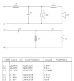
Here are specs. from B&W.
B&W P6 description
Drive units One 165mm high power Cobex cone bass
One 165mm high power Kevlar cone bass/midrange
One 25mm magnetic fluid cooled metal dome high frequency
Bass alignment Twin 4th order vented box
Also described by B&W as a 3 Way 4th order vented box system
Power handling range 50W – 200W undistorted
Frequency range -6dB frequencies 26Hz – 22kHz
Frequency response 30Hz -20kHz +-2dB
Dispersion 20Hz – 10kHz Horizontal +-2dB over 60Deg arc
Vertical +-2db over 10deg arc
Sensitivity 2.83V at 1m 90dB spl
Nominal impedance 8omh (min3.5ohm)
Crossover frequencies 150Hz, 3kHz
Dimensions Height 1000mm
Width 200mm
Depth 316mm
Net Weight 18.5Kg
Probably not. But you might find a clue in the higher-end B&W Matrix 804 design:
B&W Group North America Service & Support - Home
Looks reasonable. That 5.3uF shunt capacitor would make the Kevlar mid a bit brighter but smoother, IMO. It might get a bit peaky though unless you added some resistance. I'm sure the exact value won't be critical.
B&W Group North America Service & Support - Home
Looks reasonable. That 5.3uF shunt capacitor would make the Kevlar mid a bit brighter but smoother, IMO. It might get a bit peaky though unless you added some resistance. I'm sure the exact value won't be critical.
Attachments
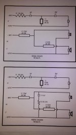
You could probably make the capacitor a bit bigger since the coil is 0.9mH rather than 1.5mH and it's the LC product you keep constant, and not add too much shunt resistance if the Le (inductance) of the Kevlar driver is around a lowish 0.6mH.
So 3.3R and 6.8uF would be a good initial guess for a substantial effect. The order shouldn't matter, but standard Radio Frequency practise is to put the big component, the capacitor, at the earth end.
I assume B&W mean 0.56R when they say R56 in the tweeter filter. Looks about right anyway. You'd might short it out to match the woofer's increased midrange output after modification. Impedance stays around 4 ohms at 4kHz, so not much different.
- Status
- This old topic is closed. If you want to reopen this topic, contact a moderator using the "Report Post" button.
- Home
- Loudspeakers
- Multi-Way
- xover mods