I have played with the idea of a Synergy horn for a while, and while it´s going to be a while until it´s completed, I thought I could share the process with you guys, and perhaps get some help along the way. Part of my motivation is to increase the interest of ABEC3. No commercial association what so ever (I have a Student licence for non-commercial use), but it´s such a powerful software that I´d really like to see it spread - so I can get advice on how to use it from other members. ") If there is interest, I can post the scripts used - just let me know. I should also mention that there I have "stolen" from various Akabak scripts made by others, read up on DIYaudio forums etc, so if somebody feels like it looks too much like something they did, let me know and I´ll be sure to mention you here (if you want ).
If there is interest, I can post the scripts used - just let me know. I should also mention that there I have "stolen" from various Akabak scripts made by others, read up on DIYaudio forums etc, so if somebody feels like it looks too much like something they did, let me know and I´ll be sure to mention you here (if you want ).
In another thread (see http://www.diyaudio.com/forums/multi-way/88237-suitable-midrange-cone-bandpass-mid-unity-horn-187.html#post4152484, and http://www.diyaudio.com/forums/multi-way/88237-suitable-midrange-cone-bandpass-mid-unity-horn-188.html#post4158855 i put some preliminary results of the simulations. I probably shouldn´t contaminate that thread anymore..
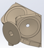
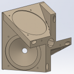
Another thing I´d like to try with this build, is to make a CD+Mid horn stub using a 3D printer. Now I haven´t checkout how expensive it will be to print something like this, so it´s a hypothesis still. The compression driver I imagine using is a DE250, while the mids are the Visaton M10s. I intend to put "pilot holes" into the print itself, and tap M3 or M4 holes into the printed ABS (or whatever material is best suited) to mount the drivers.
It seems that to get the smoothest response for the mids, a frustum without a cylindrical compression chamber first is the best choice. Now, in the sims I did not include the volume under the cone, as I don´t have the drivers yet and haven´t figured out how big that is. If anybody wants to measure the volume under the cone for the M10 mids, I´ll include that in the sim. Otherwise, I´ll order the drivers and adjust the model as required.
I think this configuration allows for maximum extension of the midranges, as it will have minimum cancellation compared to having the driver offset compared to the entry hole. The mid taps are 55mm from the CD entry, which seems to give (with an arbitrary 1" compression compression driver simulated) a first null at slightly below 2kHz. The frustum diameter is 9cm, the depth is 1.7cm and the entry holes are 1.5cm diameter.
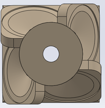
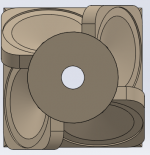
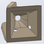
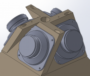
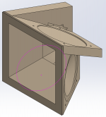
The 3D-printable part now looks like this (if it _can_ be printed - I don´t know, perhaps someone will chip in). It still need some refinement - adding pilot holes for tapping, checking for thickness, adding something to allow it to "strap on" to a wooden horn section etc. But I think it will be something like this.


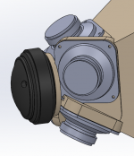
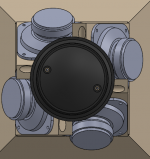
Including the drivers:

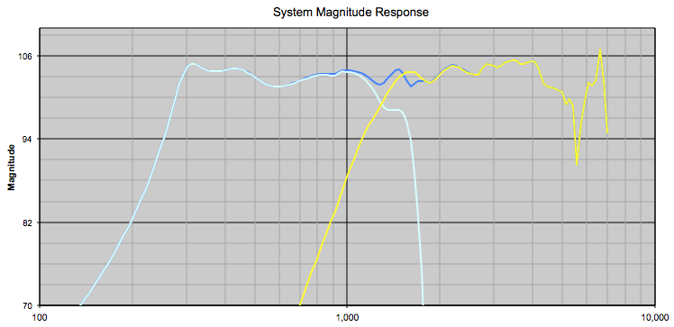
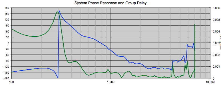
The simulated response (no crossovers, as this is cumbersome) with the big frustum instead of a cylindrical chamber first, and before adjusting for the "under the cone" volume:
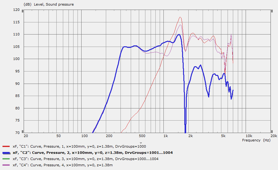
I think the simulated response looks pretty good, but it´s obvious that the driver has to be highpassed around 3-400Hz, and will cover a rather narrow range.
The next step will be to add woofers. I have room for 10 inchers (or will make room), but was hoping to get by with two woofers per side and still reach 100hz. I would really like to make this a sealed build, to keep things simpler. Any suggestion for a suitable driver?
If there is interest, I can post the scripts used - just let me know. I should also mention that there I have "stolen" from various Akabak scripts made by others, read up on DIYaudio forums etc, so if somebody feels like it looks too much like something they did, let me know and I´ll be sure to mention you here (if you want ).In another thread (see http://www.diyaudio.com/forums/multi-way/88237-suitable-midrange-cone-bandpass-mid-unity-horn-187.html#post4152484, and http://www.diyaudio.com/forums/multi-way/88237-suitable-midrange-cone-bandpass-mid-unity-horn-188.html#post4158855 i put some preliminary results of the simulations. I probably shouldn´t contaminate that thread anymore..
Another thing I´d like to try with this build, is to make a CD+Mid horn stub using a 3D printer. Now I haven´t checkout how expensive it will be to print something like this, so it´s a hypothesis still. The compression driver I imagine using is a DE250, while the mids are the Visaton M10s. I intend to put "pilot holes" into the print itself, and tap M3 or M4 holes into the printed ABS (or whatever material is best suited) to mount the drivers.
It seems that to get the smoothest response for the mids, a frustum without a cylindrical compression chamber first is the best choice. Now, in the sims I did not include the volume under the cone, as I don´t have the drivers yet and haven´t figured out how big that is. If anybody wants to measure the volume under the cone for the M10 mids, I´ll include that in the sim. Otherwise, I´ll order the drivers and adjust the model as required.
I think this configuration allows for maximum extension of the midranges, as it will have minimum cancellation compared to having the driver offset compared to the entry hole. The mid taps are 55mm from the CD entry, which seems to give (with an arbitrary 1" compression compression driver simulated) a first null at slightly below 2kHz. The frustum diameter is 9cm, the depth is 1.7cm and the entry holes are 1.5cm diameter.
The 3D-printable part now looks like this (if it _can_ be printed - I don´t know, perhaps someone will chip in). It still need some refinement - adding pilot holes for tapping, checking for thickness, adding something to allow it to "strap on" to a wooden horn section etc. But I think it will be something like this.
Including the drivers:
The simulated response (no crossovers, as this is cumbersome) with the big frustum instead of a cylindrical chamber first, and before adjusting for the "under the cone" volume:
I think the simulated response looks pretty good, but it´s obvious that the driver has to be highpassed around 3-400Hz, and will cover a rather narrow range.
The next step will be to add woofers. I have room for 10 inchers (or will make room), but was hoping to get by with two woofers per side and still reach 100hz. I would really like to make this a sealed build, to keep things simpler. Any suggestion for a suitable driver?
Attachments
-
 synergy8.png42.3 KB · Views: 2,835
 -
 synergy7.png50.1 KB · Views: 2,840
 -
 synergy6.png36.3 KB · Views: 2,805
 -
 synergy9.png106 KB · Views: 2,821
 -
![2014-12-29 20_58_24-VacsViewer - (new) - [Velocity mid ports].png](/community/data/attachments/411/411047-0b8f03fd06209dbe06133672df42ce24.jpg) 2014-12-29 20_58_24-VacsViewer - (new) - [Velocity mid ports].png30.5 KB · Views: 2,824
2014-12-29 20_58_24-VacsViewer - (new) - [Velocity mid ports].png30.5 KB · Views: 2,824 -
![2014-12-29 20_57_05-VacsViewer - (new) - [SPL].png](/community/data/attachments/411/411039-e327858e308e4f5995928530dfcbb6bf.jpg) 2014-12-29 20_57_05-VacsViewer - (new) - [SPL].png40.4 KB · Views: 2,802
2014-12-29 20_57_05-VacsViewer - (new) - [SPL].png40.4 KB · Views: 2,802 -
![2014-12-29 20_55_02-VacsViewer - (new) - [Excursion mids].png](/community/data/attachments/411/411028-c941e0e40eefa1d7334eea2ad3eef0e7.jpg) 2014-12-29 20_55_02-VacsViewer - (new) - [Excursion mids].png29.2 KB · Views: 144
2014-12-29 20_55_02-VacsViewer - (new) - [Excursion mids].png29.2 KB · Views: 144
Shapeways is one company to look up, upload the model and it will tell you the price.
They now do a lost wax, where you can 3D print it and take it to a foundry to have cast, which would work out way cheaper than printing in steel.
You might be better off getting them cut on a CNC, some complex compound angles, but wouldn't be impossible?
They now do a lost wax, where you can 3D print it and take it to a foundry to have cast, which would work out way cheaper than printing in steel.
You might be better off getting them cut on a CNC, some complex compound angles, but wouldn't be impossible?
Thanks Studio Au,
I checked a few commercial online printers:
Wow. Anyhow, I checked a few local ones here in Norway at 3dhubs.com. First one that showed up wanted 990 NOK for it, which is about 130 USD / 110 EUR. PLA is the material for that price.
Seems like local is the way to go - or - get my own printer.
I checked a few commercial online printers:
- Shapeways: 349 USD in "Strong and flexible plastic". Failed wall thickness test (i had expected that, as I need to add some more material in a few places).
- i.materialise.com: 217 EUR in Polyamide.
- Sculpteo: 608 EUR in Plastic.
Wow. Anyhow, I checked a few local ones here in Norway at 3dhubs.com. First one that showed up wanted 990 NOK for it, which is about 130 USD / 110 EUR. PLA is the material for that price.
Seems like local is the way to go - or - get my own printer.
Why would you need this to be made of metal? ABS plastic is perfectly fine for this app.They now do a lost wax, where you can 3D print it and take it to a foundry to have cast, which would work out way cheaper than printing in steel.
The question you need to ask yourself is how many iterations you will need to print before you are satisfied with the results. For example, I'm on the 3rd iteration of mid holes and bandpass chamber for mine and I need some form of phase plug as well because I'm doing a 2-way with 8" drivers. I'm sure you will do better but I did do a lot of simulation.
So yes, print that round to rectangular transition section but do as much of the rest of it in wood as you can so you can tweak it without breaking the bank!
I see in your simulation that you have a wide, extended BW for your mids. That was my initial goal as well. That is actually the easy part (unless you are using a big driver but getting high BW sim was easy with my 8" drivers because the reason I didn't realize that high BW wasn't modeled). The hard part and I think a difference maker is fine tuning the acoustic low pass filtering of the throat chamber and ports so that you have just enough BW and no more. If you can get that right with ABEC simulation and not need multiple tweaks, then my hat is off to you and I will be tempted to learn the tool.
Good luck with this project. I look forward to following your progress.
Cookie Monster,
Great work here - have you found the ABEC3 results similar to Akabak? I haven't quite been able to find time to immerse myself into the ABEC3 learning curve.
Your 3d model above looks tight - there are visible interferences on the driver mounting flange etc. you may want to move things out tad. I am in same camp with NC535 above in the use of larger mid-bass drivers to get the range from 100Hz to 1kHz with a single driver and use a two way. For example,
using a good mid like B&C 6MDN44 covers the 200Hz to 1kHz range nicely. An 8in works too as well as a 15in! I think Legis did this on his Synergy and has 80Hz to 1kHz with 15in Deltalite.
@ nc535: Yes, i understand there is a risk of an interation or three. But the advantage is, that once there is a "fit" for the particular drivers, it can be reused, also by others if they want. With my wood working skill level, it´s unlikely I can get the precision needed. Also, I figure the shorter wavelengths for the mid and CD are more sensitive to uneven surfaces, leaks etc than the woofer. So the precision for the rest of the horn can be lower without any negative effects.
@xrk971
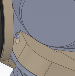
Yes, it´s tight! I had to cut away a part to be able to "slide" the driver under the mounting plate for the next driver, and also cut out an area to be able to reach the mounting screw -- see pictures.


Did you notice any other discrepancies? I do need, as mentioned, to check for material thickness around the frustum, as I suspect it´s a bit thin, but worst case I´ll make the frustum throat a bit smaller. I do need to verify if Akabak gives the same results, but haven´t gotten around to it yet...
I think a good start to learn ABEC is to just do a LEM simulation. Copy one of your akabak sims over, and learn how the different files configure different things. (One for the LEM script, one for the BEM part/solving config, one for the measurement spectra, one for the 2D fields etc). I actually tried to import the DE250 script I found online, and it was 99% compatible - there is just one keyword that is deprecated in ABEC, and I haven´t been able to dig into it to see how it should be replaced with an ABEC equivalent.
Just before posting this, I did a check for "collisions" in the model - and there is indeed one, but easily fixed. Of course - a more spacious way of mounting these mids would be to do it at 45 degree angles. But that would use more material, and cost more in printing. If this turns out not to be possible due to wall thicknesses etc, I might try that, but so far I think it´ll work.
Another thing I thought about was making a "modular" entry, where you print the "body" and mounting areas, and then you can insert frustums of various shapes and entry points to see which response works best. Could be attached with machine screws and rubber seals. If it´s easy, perhaps I´ll see if the model can be modified for this.
@xrk971
Yes, it´s tight! I had to cut away a part to be able to "slide" the driver under the mounting plate for the next driver, and also cut out an area to be able to reach the mounting screw -- see pictures.
Did you notice any other discrepancies? I do need, as mentioned, to check for material thickness around the frustum, as I suspect it´s a bit thin, but worst case I´ll make the frustum throat a bit smaller. I do need to verify if Akabak gives the same results, but haven´t gotten around to it yet...
I think a good start to learn ABEC is to just do a LEM simulation. Copy one of your akabak sims over, and learn how the different files configure different things. (One for the LEM script, one for the BEM part/solving config, one for the measurement spectra, one for the 2D fields etc). I actually tried to import the DE250 script I found online, and it was 99% compatible - there is just one keyword that is deprecated in ABEC, and I haven´t been able to dig into it to see how it should be replaced with an ABEC equivalent.
Just before posting this, I did a check for "collisions" in the model - and there is indeed one, but easily fixed. Of course - a more spacious way of mounting these mids would be to do it at 45 degree angles. But that would use more material, and cost more in printing. If this turns out not to be possible due to wall thicknesses etc, I might try that, but so far I think it´ll work.
Another thing I thought about was making a "modular" entry, where you print the "body" and mounting areas, and then you can insert frustums of various shapes and entry points to see which response works best. Could be attached with machine screws and rubber seals. If it´s easy, perhaps I´ll see if the model can be modified for this.
Attachments
Good idea on modular frustums/volume plug combo. Getting that volume plug to perfectly match the cone profile and have several smaller channels like a CD phase plug to lead the flow out to the frustrum would be key and the power of 3d printing. You may buy yourself additional 200Hz of upper bandwidth which lets the XO occur in a phase flat region. Much smoother that way.
Thanks for the tip on learning ABEC3. Just need to bite the bullet and do it.
Thanks for the tip on learning ABEC3. Just need to bite the bullet and do it.
I hear you about wood working skills - I designed mine in Sketchup and got it CNCed but now I've redone several pieces on my table saw perfectly adequately. I can't cut to much better than 1/16" but I can shave things to fit as needed. I now realize I should have done my iterations before I went to CNC. I would dearly love to have a machine in my garage, even a small one, because you need to have it right at hand to make changes in real time.
One of the changes I made, which might be useful to you was from a 1/4" thick CD mounting plate to a 3/4" thick plate. This pushed the CD back allowing me to slide the edges of the mids under it, relieving congestion, and bringing the mid port holes closer to the center of the mids. I gained 3/8" this way and could have gone another further - up to where the edge of the mid begins to intrude into the CD's tube. Of course, as the CD mounting plate gets thicker, you need to include the tube through it in the horn expansion...
With 4 small mids instead of two large ones, your mids should be pretty much centered over the ports and yield their full BW, limited only by the bandpass chamber and port. I on the other hand have to struggle for just a couple of hundred Hz extension on the high end beyond where the mids "want" to roll off when just screwed down to the horn wall.
You are showing BW out to almost 2 Khz. I understand wanting to maximize this BW but in this case it may be misguided effort. The synergy constraints on mid entry point may dictate a significantly lower crossover frequency and using bandpass effects to limit the bandwidth to just that frequency will ultimately lead to a better phase characteristic, IMO.
Cheers!
@ xrk971 - yes, I suppose the more equal the path length from the cone to the port the less internal cancellations will occur. Right now ABEC is simulating a flat piston into the frustum, which should tend to give greater deviations in path length than if the cone had been modelled properly. It will also underestimate the air volume.
@nc535 - one of the reasons the 3d drawings look so "funky" is that the drivers are perfectly centered over the entry point while still getting the entry in the corner of the horn. I need to model the mounting plate "towards the horn mouth" because the transition from 13 degrees round exit of the CD to the 60x60 square starts there. Pushing it back would just shift the entire horn back I think, unless I misunderstand your point. However, I don´t think the mounting plate needs to be 100mm in diameter -- just need enough to keep it stable and something to screw the CD onto. So I´ll probably redo that later to get more space. The bandwidth seems to be limited to the first reflection notch. (half a wavelength @ 1800hz is about 10cm, quarter wavelength is 5cm. I have the mids entered at 55 mm from the CD exit, and then one has to account for the throat of the compression driver, another 28mm there. So it would seem from the distances that the reflection would appear lower in frequency, but i would think that the horn shape reduces the apparent distance).
I did try a crossover based on a previous version, with a smaller frustum, but with a cylindrical compression chamber instead. Everything else is the same. The extra bandwidth is a benefit, as I was able to model quite good phase coherency without too much fiddling. (Whether it will work in real life is another story -- I´m very aware of the comments made by Tom and others regarding how a simulation is garbage in-garbage out.). But it´s a good starting point I suppose. But if I understand you correctly, you suggest that I either 1) move the mid ports further out - to get a lower first notch, and/or 2) make the compression chamber more "cancelling" to reduce the high frequency output to better match the crossover frequency I´ll end up using?
The higher frequency notch is due to the compression driver modelled, not because of the geometry of the horn here. The big frustum gives a smoother midrange response, so I think the crossover ripply can be reduced compared to the images above (but of course, other sources of response problems could appear that haven´t been simmed..)
Last edited:
You obviously have a much more complete model than any of us have had so no doubt will encounter fewer surprises.
Yes making the CD plate thicker does push the entire horn back, which might require a lower crossover point or adjustment of the mid entry point, but is a way to relieve congestion. And if you do push it back, then your model has to change so of course you wouldn't do it without good reason. I was pointing it out as a possible solution for the congestion you noted as it helped me in that regard.
Yes you did understand me re' the BW and crossover point issues.
My point can be seen in the crossover frequency responses you posted above. That shelving of the mid response right around crossover can be likely be smoothed out by the means I suggested. And the further out you can move the mid entry point, the less effect the holes will have on the high end response...so long as the CD doesn't have to strain to reach down to crossover.
On second thought, I think acoustic low pass filtering via the bandpass chamber and port may be a different game with small sealed back drivers. The large drivers used in two ways trap a lot more air under the cone and it seems you need this to achieve acoustic low pass filtering. With the 8FE200s I need to add a structure under the cone to displace air. You may benefit from standing your mids off the horn wall on rings to add volume to the chamber - to the point where adding incrementally more air changes the slope of the rolloff. Ideally, you would get the acoustic rolloff from the bandpass chamber to roll right into the cancellation null slope eliminating the shelf I see in your posted response. Yes, you can do that electrically but if you do it acoustically you filter out driver harmonic distortion products as well.
CNC, especially with access to the new hobby CNC gantry routers will be a lot cheaper than 3D printing
cutting "2.5D" relief patterns in sheets/blocks that you stack gives most features you will likely want
even Baltic Birch Plywood is orders cheaper than 3D printer material by volume
I would only consider few in^3 phase plugs for 3D printing
cutting "2.5D" relief patterns in sheets/blocks that you stack gives most features you will likely want
even Baltic Birch Plywood is orders cheaper than 3D printer material by volume
I would only consider few in^3 phase plugs for 3D printing
An externally hosted image should be here but it was not working when we last tested it.
These are my experimental 300Hz conical horns, I have purchased a birds mouth router bit to make it even easier and stronger
On mine the first 4" are turned to try and provide a better transition. Similar to an OSWG.
I wonder if this approach could be used? It would be cheaper than 3D printing.
What were you planning on mating the entry too?
CNC, especially with access to the new hobby CNC gantry routers will be a lot cheaper than 3D printing
cutting "2.5D" relief patterns in sheets/blocks that you stack gives most features you will likely want
even Baltic Birch Plywood is orders cheaper than 3D printer material by volume
I would only consider few in^3 phase plugs for 3D printing
what "hobby gantry routers" do you think would be up to the task and what would they cost?
@nc535: I tried adding some volume under the cone (i.e. spacing ring) as you suggested. It actually increased the peak in the upper midrange quite a lot. While I haven´t tried simming an open back midrange, I suppose you are right that these changes should be balanced with volume on the backside, which can´t be done with a closed back mid.
@jcx: I would also be interested in knowing what you mean here - I would love a tiny cnc mill on my desk.
@derfnofred: I actually tried drawing that up, but I can´t seem to do it without more interference between the mids. So I would need to increase the distance from the horn throat to make that work. But perhaps there is a way? If you have a mockup sketch I can try to adjust.
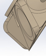
I started thinking about the mounting adapter, and how to make this 3D printable. One thing that´s difficult with 3d printers are overhangs. One rule of thumb I found is don´t make overhangs more than 45 degrees. So here is the latest iteration (see below. After uploading I noticed that I had forgotten to pattern the actual frustum around the horn, but you get the idea anyway). I think the untapped-tap holes (and access hole for the one tight corner) are the only thing that could cause an issue, so worst case I´ll do those after printing.
The entry holes are 2mm farther away from the throat now compared to the previous version. Now I need to add some bits to fasten this to the wooden horn.
I´m still wondering what kind of woofer would work from 300-400hz downwards.
Is there a point, even -- adding a woofer? Or should I just make the horn smaller (enough to control dispersion for the mids), and add a bass bin? I suppose the only reason to add it to the horn would be if you had some kind of directivity control at these frequencies?
@jcx: I would also be interested in knowing what you mean here - I would love a tiny cnc mill on my desk.
@derfnofred: I actually tried drawing that up, but I can´t seem to do it without more interference between the mids. So I would need to increase the distance from the horn throat to make that work. But perhaps there is a way? If you have a mockup sketch I can try to adjust.
I started thinking about the mounting adapter, and how to make this 3D printable. One thing that´s difficult with 3d printers are overhangs. One rule of thumb I found is don´t make overhangs more than 45 degrees. So here is the latest iteration (see below. After uploading I noticed that I had forgotten to pattern the actual frustum around the horn, but you get the idea anyway). I think the untapped-tap holes (and access hole for the one tight corner) are the only thing that could cause an issue, so worst case I´ll do those after printing.
The entry holes are 2mm farther away from the throat now compared to the previous version. Now I need to add some bits to fasten this to the wooden horn.
I´m still wondering what kind of woofer would work from 300-400hz downwards.
Is there a point, even -- adding a woofer? Or should I just make the horn smaller (enough to control dispersion for the mids), and add a bass bin? I suppose the only reason to add it to the horn would be if you had some kind of directivity control at these frequencies?
Attachments
It seems to be a general thing to get that peaking when you have enough air mass for effective filtering. I see it in my mids sim as well as in the slot loaded bass bin I'm designing for use with my horn. I think nothing of it because it only takes a single DSP PEQ to flatten it out. Same thing I suppose for the big peak that shows on the M10 data sheet.
There is an optimum sealed back chamber volume for optimizing the low end response. It has to with reactance annulling. There is a formula around, for exponential horns at least, but its easy to find the best volume by simulation. This makes a big difference for my 2-way horn where I want the low end to reach down to a sub or base bin but I don't think it matters all that much for the mids of a 3 way.
What woofers you use depends on what you have room and budget for. Bill Waslo used 6.5" woofers in his CoSynes with 2" mids. Some Danley models use multiple 15's. I don't think those Visaton M10s reach low enough that you wouldn't want woofers in the same horn. I think if you choose mids that extend down to 250 Hz or so then you can make the case for woofers in a base bin below the horn. 3FE25's may get you there instead of the M10's but you'd need to fab rear chambers for them. Dayton also has a 3" mid that others have recommended.
A single woofer in a base bin is cheaper than two in the horn and, with Hoffman's law working for it, may have higher output. This is essentially what I'm doing. My 8" mids do extend below 100 Hz but I will overlap them with my base bins perhaps as high as 200 Hz to combat ceiling nulls and height modes. If it passes WAF, mild objection already noted, I'll will go MTM with the woofers but that makes for a tower about 6' tall. The base bin extends down to 30 Hz. In a horn I'd lucky to get within an octave of that.
I found some hobby class desktop CNCs for roughly $2K for a 2'x2' to $4K for a 2'x4' capacity. I lost the link or I'd give it to you. This is soooo tempting but I'm going to compromise by making tool paths for some one else's machine.
Apparently you can get a pretty good 3D printer for a very affordable $1K but I really don't want a plastic horn, perhaps a plastic insert for the back end if I can figure out how to use one with my vastly different design.
Cheers,
Jack
Last edited:
@Studio Au: Beautiful work! The birdsmouth bits look very useful, I agree. What are the dimensions of that horn? You say 300Hz, but what kind of driver covers that kind of range? Or do you have hidden midranges somewhere?
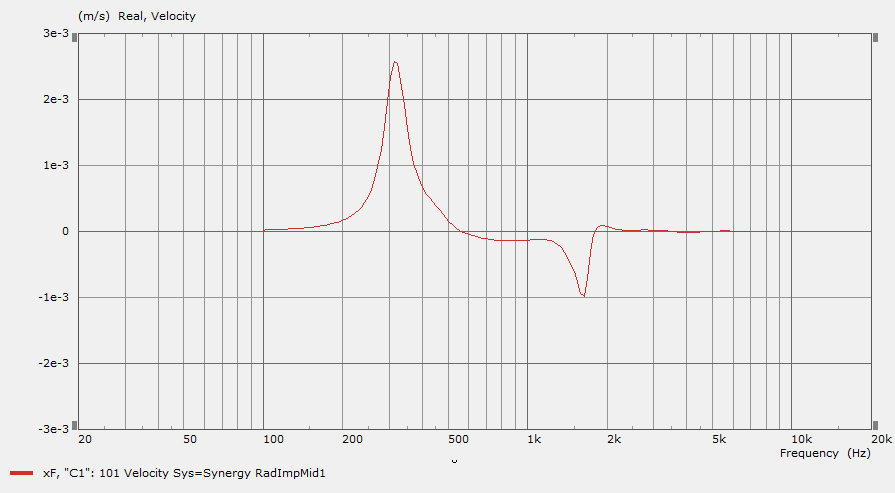
@nc535: You are right. So I´m imagining adding some woofers, and have the transition from controlled directivity to omni within the woofers range. So if the horn controls directivity to say 300Hz, I can have woofers covering 80-400, and the M10s covering the gap up to the compression driver. They will work in a rather narrow bandwidth then. As mentioned earlier, there is a huge spike in excursion and port velocity for the mids around 200hz, so that frequency is clearly too low for the mids in this configuration, unless the sims are wrong of course.
@ Winslow & xrk971: Thank you for your tips - but why do you recommend different mids than the M10? I kind of felt like the mids were OK - is there anything you see that I don´t? In my sims I have crossover points @ 1100Hz for the mids and 1300Hz for the CD.
Last edited:
- Status
- This old topic is closed. If you want to reopen this topic, contact a moderator using the "Report Post" button.
- Home
- Loudspeakers
- Multi-Way
- Synergy horn - 3d printing entry?