I have a set of old Fostex studio monitors, the RM780's.
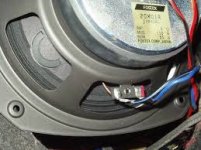
They have an adjustable Lpad on the tweeter, it says AT40-8ohm.
I re-did the crossover and replaced the leaky caps with some polys and replaced the L-pad pot with fixed resistors.
Calculated the levels and went with 4ohm in series and 8ohm in parallel because it is an 8 ohm planar tweeter.
Question is when I measure the L-pad the setting where 4ohms is in series then there is 16 ohms in parallel.... same for both pots.
If its an 8 ohm tweeter and a lpad pot for 8ohms why the funny reading?
What I means is than using an online lpad calculator I get for a 6db cut I should use 4ohm is series and 8ohm in parallel when dealing with an 8ohm tweeter..
Thus maintaining an 8ohm load (8ohm+8ohm in parallel=4ohm with 4ohm in series maintains an 8ohm load).
The pot however puts 4ohm in series and 16 ohms of resistance in parallel with the 8ohm tweeter...
makes sense?
Thus maintaining an 8ohm load (8ohm+8ohm in parallel=4ohm with 4ohm in series maintains an 8ohm load).
The pot however puts 4ohm in series and 16 ohms of resistance in parallel with the 8ohm tweeter...
makes sense?
Nope I am measuring while it is sitting on my desk removed from the speaker....
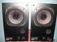
here is the speaker:
I am measuring while it is sitting on my desk removed from the speaker....here is the speaker:
Attachments


Last edited:
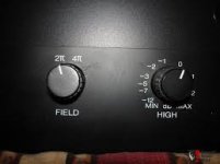
As you can see in the pics the pot is adjustable from -12 to +2 db.
But the crossover would rely on a constant impedance or else the xover point would change with adjustment of the pot no?
When I adjust the pot so that there is 3.5 ohms in series with the driver there is then around 21 ohms in parallel.
These numbers dont seem to jive with the lpad calculators I have found online, does fostex know something I dont know?
Yes and that's why it's an L-Pad not a pot.But the crossover would rely on a constant impedance or else the xover point would change with adjustment of the pot no?
Yes as one goes up, the other goes down to maintain that constant impedance.When I adjust the pot so that there is 3.5 ohms in series with the driver there is then around 21 ohms in parallel.
I'm not sure how to reverse engineer an L-Pad, I have always used the online calculators like you.These numbers dont seem to jive with the lpad calculators I have found online, does fostex know something I dont know?
Not necessarily answers, but maybe just some ideas to look into -
There may possibly be some wear and tear, or dirt and dust on the Lpad, which might affect its output on either or both taps.
I don't know how these things are constructed internally, so I'm not sure if they are strictly resistive elements or if they have some inherent reactive (inductive) component.
You could measure the Lpad values for various positions. The effective attenuation may not be as constant as expected. If you use a multi-meter, you will likely get a magnitude value, but the Lpad values may be frequency dependent. Nonteheless, I would guess that it is likely that one position might give the amount of attenuation desired.
Is the impedance of the tweeter constant (i.e. resistive)?
Also, I would hesitate to trust the -12 to +2 dB scale as anything more than approximate.
Although the theory of continuously varying the input and shunt resistance of an L-Pad to maintain constant resistance is nice, my impression is that most of the available units only roughly approximate that ideal. I think they use linear taper pots and so the ability to maintain flat resistance across the range is limited.
Think of it as an "aspirational goal".
The one exception would be old studio 600 Ohm attenuators, but they used switches and banks of resistors.
David
Think of it as an "aspirational goal".
The one exception would be old studio 600 Ohm attenuators, but they used switches and banks of resistors.
David
- Status
- This old topic is closed. If you want to reopen this topic, contact a moderator using the "Report Post" button.
- Home
- Loudspeakers
- Multi-Way
- Strange reading on Fostex L-pad....