I'm having trouble getting my box tuning right. The details are:
If I measure it via impedance, I get about 46Hz (as designed) and all subsequent near field port and woofer measurements scale and sum well to get a response and f3 similar to my simulated response.
If I measure it via the acoustic null method, I get about 40Hz (with the port above) and subsequent port and woofer measurements do not sum well. This gives a hump in bottom end response and also f3 seems too high compared to simulations.
If I adjust the port length to get 46Hz tuning (via acoustic method) I want, port level ends up too high even after applying port correction of 20log(port_diameter/woofer_diameter).
Box (16.5L net volume) is lined with 25mm acoustic foam and port is a reasonable size (62mm internal) for woofer (Peerless 830883 135mm effective diameter). Woofer has a phase plug. Rough calcs for QL are around 3.2.
I would normally just take the impedance measurement tuning and not worry, but this is for a University assignment and I want to understand why and get it right.
Any Ideas or references to books, papers etc would be greatly appreciated.
The problem with measuring the acoustical null of a vented box Is that there is always some crosstalk between vent and woofer. The mic may be very near to one but it isn't that far from the other. This will shift the measured null. I would trust the impedance curve measurement and you can also look for a visual null in woofer excursion as confirmation.
Because of this crosstalk I have never had good luck with nearfield summed response (while acounting for relative areas). A better technique is to put the mic in the box and correct the measurement with a 12 dB per Octave tilt. (highpass)
Good luck,
David
Because of this crosstalk I have never had good luck with nearfield summed response (while acounting for relative areas). A better technique is to put the mic in the box and correct the measurement with a 12 dB per Octave tilt. (highpass)
Good luck,
David
With a resonance box, quite different relations among speaker impedance and speaker output.
When last I learned about these boxes (maybe 50 years ago being the last time I was interested), they were tuned for the driver free-air resonance. Their design intention was to nullify that resonance and in the process, two new peaks on either side of where the original lay materialized, somewhat illusory-like but really there.
However housed, the impedance curve should be a good analog of cone motion around resonance. But as far as the sound output, whole different story again vis a vis cone motion when you are using a resonance box. Above resonance, the port and cone add but below resonance they subtract from one another. Some like that idea, some don't.
Ben
Last edited:
Hi Alf82,
You will find the procedure that Speakerdave referred to here;
http://www.gilszkilabor.hu/elektroakusztika/dobozban/ls_measure.pdf
At the end of the paper, the author (Richard Small) describes how to make measurements on closed and vented enclosures and also the approximate measurement of enclosure absorption losses.
Also, don't forget that the acoustic f-3dB does not equal fb!
Peter
Thanks all for your input! References to books/papers are most welcome too!
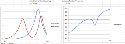
I have included a pic of my measured data imported into excel for calculations for Fb and QL etc. Note the port length for these plots is different than for the details posted above but the difference in electrical and acoustic measurements is still there.
@Ron E- The null is reasonably deep- see the pic. Should be easily deep enough to measure. Phase inversion in the impedance trough between the peaks is at 44.5Hz- closer to acoustic measurements but not 43.03Hz either. Is my low QL likely to be due mostly to air leakage around the phase plug or have I misunderstood something? All driver and terminal openings are gasketed and pipe ports blocked with very well fitting pipe caps for measurement.
@speaker dave- The design is a 2.5 way with separate enclosures for each woofer. One has a rear port while one has a front port however the results are similar for both. I would expect a difference between the rear vented woofer and the front vented woofer if crosstalk was the cause- I am more than happy to be corrected though! The graphs posted are from rear ported measurements.
@bentoronto- having selected the ported box for the design I am just worried about accurate measurements at this point rather than preferences for different enclosure types. The impedance peaks are there as you say- see the measurements. The problem is the tuning frequency calculated from them does not correlate with the tuning frequency given by the dip in cone excursion. It is this discrepancy I am asking about.
Attachments
The problem with measuring the acoustical null of a vented box Is that there is always some crosstalk between vent and woofer. The mic may be very near to one but it isn't that far from the other. This will shift the measured null. I would trust the impedance curve measurement and you can also look for a visual null in woofer excursion as confirmation.
David
speaker dave,
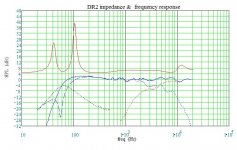
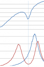
I was also wondering about the mismatch between vent and the woofer null. Attached are measurements of a 2-way bookshelf speaker. Is this what you are talking about?
Measurements were taken with the mic approx 1/4 inch from vent opening, and also 1/4 inch from dust cap.
Attachments
Thanks all for your input! References to books/papers are most welcome too!
@speaker dave- The design is a 2.5 way with separate enclosures for each woofer. One has a rear port while one has a front port however the results are similar for both. I would expect a difference between the rear vented woofer and the front vented woofer if crosstalk was the cause- I am more than happy to be corrected though! The graphs posted are from rear ported measurements.
.
Yes, you might expect to see a difference between nearfields of a front port vs. a rear port, since proximity to the woofers would be different. I still think that the offset is most likely from crosstalk. Are you saying that you can overlay the vent curves (you only show one) and they both have the same vent frequency?
Not sure how you divided your cabinet but I assume the volumes are equal.
Your own evidence suggests that the box tuning judged by the impedance curve is more accurate than judged via the woofer nearfield. I didn't fully understand how you were getting two different summed responses as the acoustical curves you are adding are the same even if your estimate of vent frequency is uncertain.
The definitive answer would be to use a laser for cone excursion and compare that to the woofer nearfield. Both your measurement (and Dave R's) show a response null a little lower than implied by the impedance curve, and this would follow from woofer and port being in phase above resonance and out of phase below. Therefore crosstalk will tend to add output above resonance and subtract below, shifting the null downwards as we see.
In truth, I have never achieved great accuracy with T/S modeling and have just learned to live with discrepencies on the order of what you are showing.... That is, build, measure, then adjust tuning if necessary to get a best fit to the intended response. Remember that T/S calculations assume full 2 Pi loading and woofers with no inductance, so ultimate accuracy is illusory (nice word!).
Regards
Hi Alf82,
You will find the procedure that Speakerdave referred to here;
http://www.gilszkilabor.hu/elektroakusztika/dobozban/ls_measure.pdf
Peter
Thanks for the link, Peter. Don Keele had told me about the tweeter in the box trick, although it looks like he got it from Small, who borrowed it from Thiele.
Damping material in a vented box makes things hard to relate to textbook calculations. In an undamped box, you can measure the sealed box and ported box resonances and derive the tuning frequency, as outlined in "Testing Loudspeakers" and in "Theory and Design of Loudspeaker Enclosures"
Why not share your data - the woofer parameters and box specs and people can check your calculations for themselves.
Why not share your data - the woofer parameters and box specs and people can check your calculations for themselves.
Sorry about my delayed responses, my posts are still being vetted by the mods as I am new so they are a little sporadic.
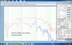
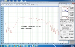
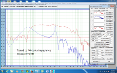
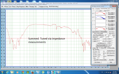
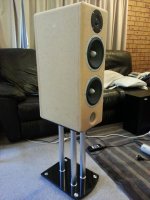
Here are the vent, woofer and summed near field responses for my bottom woofer which has a front port. Cabinet net volume is 16.5L. 5 walls lined with this product:Sonex Acoustic Sheet 25mm | Foam & Rubber Products
Ports have flared inlet and outlet as per pic. Construction is of 18mm MDF.
I have included plots for the system fb=46 hz according to electrical measurements and tuned to 46hz according to acoustic measurements and summed response for both.
Attachments
Dave, you don't need to put the microphone all the way inside the box in order to use Small's method.
Let's look at the physics; The inbox volume displacement has to be equal to the sum of the driver and vent volume displacement. Also the farfield pressure is proportional to the driver plus vent volume acceleration. Displacement and acceleration are related by double differentiation, hence a 12dB/Oct slope.
So in theory whether you measure farfield pressure or in-box double differentiated pressure, you get the same result.
Now think about the vent output: it is an acoustic mass driven by a force, that force being provided by the in-box pressure. Therefore the acceleration of the vent , from F=ma, is directly proportional to the in-box pressure. The fun fact here is that if we want to measure the low frequency response of a reflex box, we need only measure the vent nearfield response and double differentiate it: We do not need to measure the driver response!!!!
At first blush this seems unlikely, but I came to this thinking first when measuring the coupled cavity systems, after discussions with Phil Knight. He didn't believe me at first either!
But it is easy to verify both in practice and theory, and becomes obvious also when you look at the equivalent cct model for a vented box.
It also saves you the problem of measuring vent and woofer, then scaling by effective area, then adding them together. Because the frequencies below vent tuning are in opposite phase and gradually subtracting as you go down in frequency, it is difficult ot get a good clean response from the summation. My method totally avoids this")
In practice, I put the microphone just inside the vent, using a mic of small enough diameter such that it doesn't effect vent area, or produce airflow obstruction.
Andrew
Let's look at the physics; The inbox volume displacement has to be equal to the sum of the driver and vent volume displacement. Also the farfield pressure is proportional to the driver plus vent volume acceleration. Displacement and acceleration are related by double differentiation, hence a 12dB/Oct slope.
So in theory whether you measure farfield pressure or in-box double differentiated pressure, you get the same result.
Now think about the vent output: it is an acoustic mass driven by a force, that force being provided by the in-box pressure. Therefore the acceleration of the vent , from F=ma, is directly proportional to the in-box pressure. The fun fact here is that if we want to measure the low frequency response of a reflex box, we need only measure the vent nearfield response and double differentiate it: We do not need to measure the driver response!!!!
At first blush this seems unlikely, but I came to this thinking first when measuring the coupled cavity systems, after discussions with Phil Knight. He didn't believe me at first either!
But it is easy to verify both in practice and theory, and becomes obvious also when you look at the equivalent cct model for a vented box.
It also saves you the problem of measuring vent and woofer, then scaling by effective area, then adding them together. Because the frequencies below vent tuning are in opposite phase and gradually subtracting as you go down in frequency, it is difficult ot get a good clean response from the summation. My method totally avoids this
In practice, I put the microphone just inside the vent, using a mic of small enough diameter such that it doesn't effect vent area, or produce airflow obstruction.
Andrew
Hi Dave.
Yes, 1/4" mic is generally sufficient. If you want to get pedantic, I leave this in place when I measure the impedance for calculating the response as a cross check, so that the tuning is consistent.
As far as mic placement goes, the further into the vent, the higher the sound pressure until it reaches a maximum once inside the box, so it just changes the signal to room ratio.
AJ
Hi Andrew, I may be demonstrating ignorance here, but is there a way to double differentiate an .frd or .txt of a frequency response in a program like Excel or would it have to be in something like Mathcad? It seems like it would be a nifty addition to the current programs such as Holmes, REW, Soundeasy, ARTA, etc.
- Status
- This old topic is closed. If you want to reopen this topic, contact a moderator using the "Report Post" button.
- Home
- Loudspeakers
- Multi-Way
- Measuring fb: impedance vs acoustic