I think is has become necessary to emphasize that my primary objective as stated in the second sentence of my OP, is to determine the difference in the power dissipation in a tweeter when using a BW3 compared to a LR4 Xover. In order to establish this, I asked for info on a suitable signal source that replicates the spectral density of normal music program material.
I am not asking for a signal source to determine the maximum dissipation in a tweeter. Providing links to existing designs and/or Xover schematics misses the point completely.
Peter
PS. My hearing aid clips well before my amps!!
Hi,
Missing the point ? Who ? You ...
The answer is nothing worth bothering about, and variations
of spectral density make very little difference to the difference
in total power dissipation, that much should be very obvious.
Power dissipation in a tweeter is never the point in any practical
analysis of design, tweeter excursion very much is the total point.
If you can't see the point your barking up the very wrong tree.
Existing designs are the reality, not something to ignore.
Your calculations are pragmatically meaningless, for say
a tweeter with a 1st order electrical filter that then rolls
off with a perfect BW3 high pass acoustic response.
(The design goal for most cheap tweeters.)
Still the answer to your basic question is not much,
for whatever sensible spectral density you choose.
rgds, sreten.
Last edited:
Hi Charles,
The results of an earlier LtSpice simulation is attached (Fig.1) and shows the power dissipated into an 8 ohm load using white and pink noise via various 1.5KHz Xover filters. In both white and pink noise sims, the generator output level was first adjusted to give 1 watt dissipation without a Xover, into an 8 ohm load before inserting the various types of HP Xover filter.
As you can see, when a pink noise source is used, a BW3 Xover, compared to a LR4, increases the dissipation in the load by 10.7%. When a white noise source is used, the power increase is much less at only about 2.8%. Will detail LtSpice schematic tomorrow and add a few more comments.
BTW, I should have highlighted the word "difference" instead of "dissipation" in my post#19
Peter
Attachments
Peter,As you can see, when a pink noise source is used, a BW3 Xover, compared to a LR4, increases the dissipation in the load by 10.7%. When a white noise source is used, the power increase is much less at only about 2.8%.
White noise is equal power per Hz, pink noise is filtered white noise giving equal power per octave. A white noise source by definition has less overall power than a pink noise source of equal HF power.
The difference between the two is similar to listening to the "hiss" between radio frequencies on an analog radio receiver, or listening to a jet engine at several miles distance, the jet engine sound at a distance is more like pink noise (due to HF air absorption), but up close more like white noise.
Art
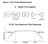
I question your methodology there, Peter. Interesting as your 10% BW3/LR4 result is, IEC 268-5 uses pink noise with a downward slope above 5kHz. That seems more representative of music's real spectral content.
JBL and SEAS both use it. But in the case of tweeters, with a 2.5kHz 12dB slope on the pink noise. H1212-06 27TBFC/G
My thinking is more intuitive here, but I'd say that BW3 stresses a tweeter a lot more than LR4. I'd think 30-40%. After all, it has an octave where power is doubled, and that octave is where the power is high. Of course, that is still better than the SEAS 12dB/octave slope at 2.5kHz, so we should be looking at something still above 90W program for their tweeters. But if you are crossing over at 1.5kHz, that will reduce power handling and increase tweeter diaphragm displacement even more.
Attachments
The music and audio signal fed to the HF end of the tweeters passband is mainly transients.
The heating power in these short transients is low. As transients they have gaps between events.
The average power fed to the tweeter in the top octave of 10kHz to 20kHz will be very low cf the remainder of the audio band.
The peak instantaneous power can be very high.
The heating power in these short transients is low. As transients they have gaps between events.
The average power fed to the tweeter in the top octave of 10kHz to 20kHz will be very low cf the remainder of the audio band.
The peak instantaneous power can be very high.
Last edited:
I don't know if this is off-topic, but my own experiments with tweeters suggest there is very little significant output above 3kHz, and your ear isn't very directional with locating high frequencies.
I found this vertical tweeter crossed over at 3kHz, bouncing mainly off the ceiling I suppose, sounded pretty good. Just adds a bit of air. Most of the music was coming out of the woofer if I put my hand over the tweeter!
Interestingly, I found the tweeter was very sensitive to exact flush mounting when facing forwards.
Attachments
Hi Charles,
As promised, please find attached Fig.2 showing the schematic I’m using for the simulations. Fig.3 shows the frequency response of the 4 types of filter used.
As you can see in Fig.2, I used a sine wave generator (V4) as a source, followed by a voltage dependant voltage source (E2) with a –3dB/oct transfer function to give a pink noise spectra at its output. One other point that I noted was that the difference in dissipation between the various types of filter was relatively small for both white and pink noise sources, but this may change with Sytem7’s suggestion of using the IEC 268-5 standard as a source. Will let you know results as soon as I have enough time to fit it into my schedule.
Peter
Attachments
Intuitively I'd agree with System 7 in post 24 and definitely with Andrew T.
Probably something to bear in mind when designing large 2ways.
Personally I like active 3ways since one can choose drivers which are flat for at least an octave past the xover points in which case electric slope = acoustic slope for where it matters most. As for slopes themselves I keep coming back to L-R4.
Have you thought of trying a range of music as signal?
Wouldn't necessarily be easily replicable for others but it might give you a better idea of the effect in a situation typical for you.
- Status
- This old topic is closed. If you want to reopen this topic, contact a moderator using the "Report Post" button.
- Home
- Loudspeakers
- Multi-Way
- Tweeter dissipation