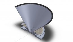
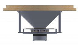
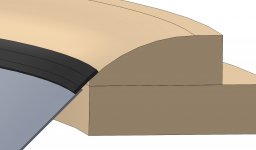
Still have to figure out a few things, but this design is pretty close. The compression driver mounts onto the back (currently sized for the DE250) and the screws go in from the front. Once the screws are tightened, the hole caps go in to restore the seamless profile.
I've run the motor through FEMM and it looks like I can get at least 0.8T through the gap using N40-grade disc magnets. The center pole hides a copper sleeve. What helps is that xmax has to be limited to +/- 0.5 mm (or some other arbitrarily low figure) to curtail modulation of the compression driver's output, so there are basically no excursion-dependent non-linearities. In case you're wondering, this MUST be used on top of another 15"/18", crossed 4th-order at 250-300 Hz to minimize excursion.
The basket will probably be made out of a few aluminum shafts connecting plates together, sort of like how Audio-Technology does their Flex Units.
Not quite sure what to make the cone out of. Paper is probably the easiest method, but the issues of shape tolerance and mediocre stiffness concern me. I'd like to try a sandwich cone out of either magnesium or carbon fiber, over Rohacell, but both of those materials I'm not familiar with.
Attachments
Neat ideas and ambitious but I think you idea for a ring of Nd slugs and a paper cone can work. You may want to check out the 5MR450NDY driver that has a huge Nd motor and a stiff paper cone and suspension. I use it in a horn and it like the sound. More info here:
http://www.diyaudio.com/forums/full-range/259293-prv-5mr450-ndy-fast-applications.html
Maybe an OS horn can be coupled with this driver in a larger throat?
http://www.diyaudio.com/forums/full-range/259293-prv-5mr450-ndy-fast-applications.html
Maybe an OS horn can be coupled with this driver in a larger throat?
In terms of dispersion, I don't know if there has been any reports that indicate off-axis response is significantly different for a deep cone than a shallow cone, as long as the cone breakup has not yet come into play.A deep straight cone tends to be stiffer than a shallow one. But when it breaks up (up to a certain frequency), it's probably more severe, thus a higher and narrower peak. And it's slightly heavier and inferior in dispersion.
Hopefully, the cone won't break up until at least 1500 Hz, which is about an octave above. The first resonance mode can be shifted up as well, by adding stiffening ribs to the rear of the cone. Very easy to do after assembly, with this type of construction.
and inferior in dispersion.
What does that mean?
The analysis that I did in my book implied that if the cone is rigid, i.e. no waves moving IN the cone body, then the effect of a deeper cone is to widen the response.
The analysis I did in my head ten seconds ago, concurs.
What does that mean?
Sorry I almost forgot it's not allowed to use casual terms here.
Inferior dispersion usually refers to narrower and/or chaotic changes of radiating angle.
That's just a rough observation to various (imperfect) speakers over the years. Again, no data to prove anything. So, let's drop it.
Can't do that. Putting a "flat" on the cone, especially so far away from the voice coil, is going to lower the breakup frequencies due to the combination of higher inertia without a corresponding increase in stiffness.What about adding a flare to the cone 2" or so from the surround, like a radius termination on a proper waveguide?
I do have a proposed solution coming up.
When I was a kid my brother and I made a huge 24" cone out of Bristol board and glued it to the cone of a 10" Jensen fullrange. We were amazed at how well it worked at producing bass even out of the box in free air. Almost like a dipole speaker. Maybe look at modifying an Eminence Beta 12CX by gluing on a bigger cone. Then your just left with extending the basket out and adding a surround.
Bad transitions between the driver, the center pole, and the cone. Also the pattern is too wide, and if one is to go to all this trouble anyway, they may as well start with a bigger seamless cone to get pattern control down to where diminishing effects come into play (e.g. 18" per Geddes).When I was a kid my brother and I made a huge 24" cone out of Bristol board and glued it to the cone of a 10" Jensen fullrange. We were amazed at how well it worked at producing bass even out of the box in free air. Almost like a dipole speaker. Maybe look at modifying an Eminence Beta 12CX by gluing on a bigger cone. Then your just left with extending the basket out and adding a surround.
Last edited:
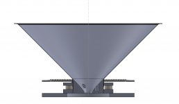
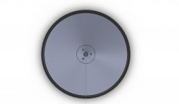
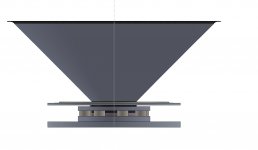
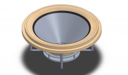
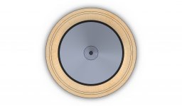
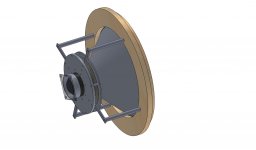
Solved. The mounting flange fixes the "free" end of the surround and incorporates a 75 mm radius to reduce diffraction at the mouth. It has a recess to rear-mount flush fit into a cutout of 600 mm. I believe making it out of MDF would be the most economical way to achieve dimensional stability with adequate strength.What about adding a flare to the cone 2" or so from the surround, like a radius termination on a proper waveguide?
Attachments

Last edited:
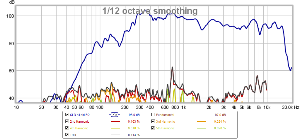
Very cool. What will you make the large cone from? Note that my experience with thin materials for a horn or waveguide show that a lot of harmonic distortion will be present due to vibrations and resonances in the waveguide material itself. Once I sandwiched it with a flexible constrained layer damping the HD went down dramatically. What you have here may be a challenge as it has to be light and thin to be the mid-bass driver and stuff and heavy enough to not support resonances from the central CD.
Here is an example of the reduction I got from CLD in a tractrix made of foam core.
Before CLD:
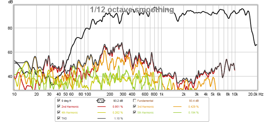
After CLD:
More info here: http://www.diyaudio.com/forums/full-range/259293-prv-5mr450-ndy-fast-applications-13.html
Here is an example of the reduction I got from CLD in a tractrix made of foam core.
Before CLD:
After CLD:
More info here: http://www.diyaudio.com/forums/full-range/259293-prv-5mr450-ndy-fast-applications-13.html
Inferior dispersion usually refers to narrower and/or chaotic changes of radiating angle.
"Inferior dispersion" = narrower, got it

I can't see that anything will excite modes of vibration in the cone aside from the force on the voice coil itself. The compression driver is clamped into a fairly solid steel plug.Very cool. What will you make the large cone from? Note that my experience with thin materials for a horn or waveguide show that a lot of harmonic distortion will be present due to vibrations and resonances in the waveguide material itself. Once I sandwiched it with a flexible constrained layer damping the HD went down dramatically. What you have here may be a challenge as it has to be light and thin to be the mid-bass driver and stuff and heavy enough to not support resonances from the central CD.
The cone should be made out of spun aluminum, I suspect. As for increasing the modal frequencies, the two options open to me are making two cones out of a thinner material and sandwiching a structural foam core in between, or, adding stiffening ribs to the backside, a la the Kef Uni-Q woofer.
I would be tempted to make the lower of the two mouth rings from aluminium. I have seen thicker MDF rings of that size distort. Also a lot of open end grain MDF will absorb moisture.
The compression from bolting the basket legs to MDF will make it hard to maintain exact symmetry. Especially after bolting them on and off a few times and with the weight stress.
Cool project btw...what are your thoughts on modifying (butchering) a suitable existing driver for experimentation?
The compression from bolting the basket legs to MDF will make it hard to maintain exact symmetry. Especially after bolting them on and off a few times and with the weight stress.
Cool project btw...what are your thoughts on modifying (butchering) a suitable existing driver for experimentation?
Last edited:
- Status
- This old topic is closed. If you want to reopen this topic, contact a moderator using the "Report Post" button.
- Home
- Loudspeakers
- Multi-Way
- 18" 90-deg OS WG coaxial (design)