My goal here is to use my current midwoofers (TD15m) from 80-1000ish and have controlled directivity from 300hz up. In my room I'd like to have a 60° beamwidth and I'd make elliptical os waveguides to match, but I won't settle for anything more than 90°.
There's really three ways that I see to do this: dipole, cardioid(or variations thereof), or some big horns. I don't like dipole because that's a 120° pattern and I don't like the rear energy bouncing off the front wall....been there and done that. Horns will be another project. So that leaves cardioid. I've seen several passive resistance diy designs online, but nothing that really looks good over 400hz.
Being the pc dsp dork that I am I thought I would try an active cardioid using smaller drivers on the rear or sides of the cab. Linkwitz says a cardioid can be made with 2 monopoles back to back, with the rear driver out of phase and delayed the time it takes to reach the front baffle plane. I'm using some junk 2cu ft sealed cabs, old (early 80's...older than me!) 15" Eminence woofers and 8" Vifa hifi drivers. The first implementation was a single 8" on the back. I tried different delay settings, levels, as well as hi and low pass on the 8" but could only get good results up to 400hz. Above that things get goofy. Sorry didn't save the data.
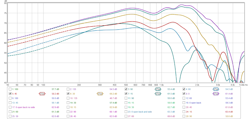
I wasn't surprised considering the cab is 15" deep which is more than a wl at 1khz where I want to xo.....so I put an 8" on each side of the cab about 3.5" from the front baffle plane. I ended up delaying the main 15" by .25ms (which I thought was odd). The 8's are out of phase, -9dB in my dsp and have a first order low pass at 700hz. Here's 0-90°:
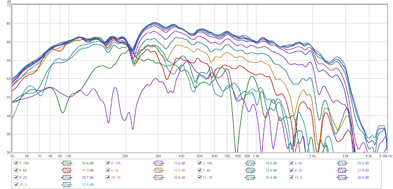
And a polar plot:

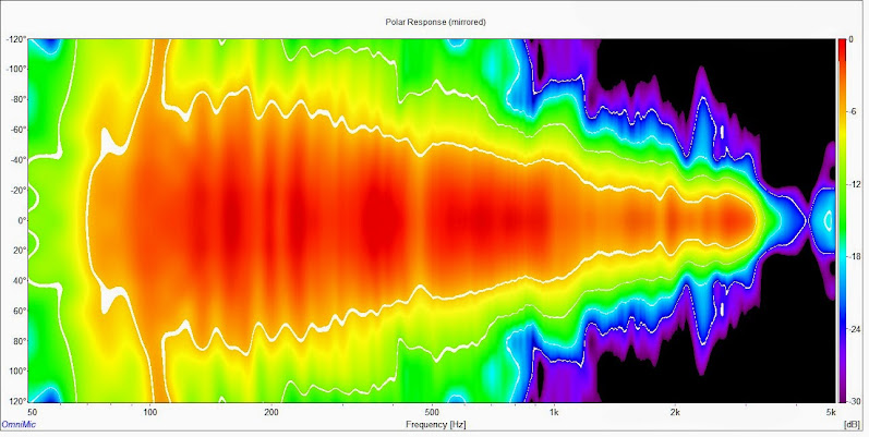
Sonogram? Why not:
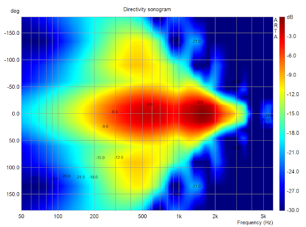
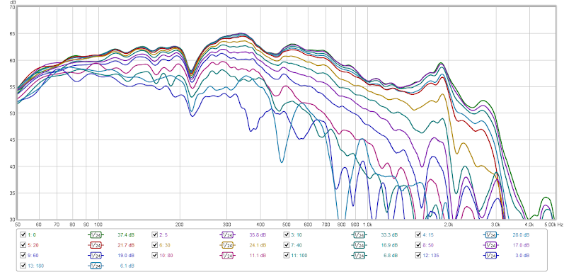
Not bad! Right around 90° or less from 300 up. As you can see it's really only cardioid at 1khz with a good bit of rearward energy as you go down in freq. I'd like to see some better rear attenuation, and that 90° measurement is funny. These cabs already had a 12"x12" hole in the back that I covered with mdf, so I opened it up and stuffed them with bonded logic:

Here you can see that it didn't really affect the forward response, but attenuated the rear a good bit and tends toward a hyper-cardioid. Nice.
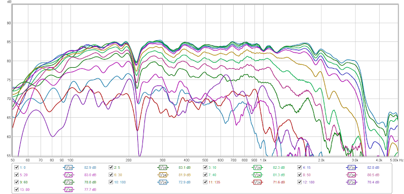
I did a lot of playing around with this. I could get a 60° beamwidth by shaping the side drivers with hi and low shelving filters, but it would create some serious lobing at 90° and beyond. Ideally I would have a driver on the back as well. That would need a channel of it's own for a different delay and that's getting too complex. We're talking 5 channels at that point for a 2.5 way speaker
I've got enough data at this point to feel comfortable moving forward with this. Any ideas on suitable 8" drivers for the directivity control? They're down quite a ways in level, and since they aren't really contributing to the direct sound they don't need to be anything special. I'm thinking the Dayton PA's. Also, any thoughts on the closed vs. open back? I'd like more attenuation to the rear but the open back does have more lf roll-off.
Measurements unfortunately were done in my garage, ground plane with a 5ms gate. I wanted to do them outside but it kept sprinkling off and on all afternoon, though I think it's good enough to see the general trend. Hopefully I can get out tomorrow.
There's really three ways that I see to do this: dipole, cardioid(or variations thereof), or some big horns. I don't like dipole because that's a 120° pattern and I don't like the rear energy bouncing off the front wall....been there and done that. Horns will be another project. So that leaves cardioid. I've seen several passive resistance diy designs online, but nothing that really looks good over 400hz.
Being the pc dsp dork that I am I thought I would try an active cardioid using smaller drivers on the rear or sides of the cab. Linkwitz says a cardioid can be made with 2 monopoles back to back, with the rear driver out of phase and delayed the time it takes to reach the front baffle plane. I'm using some junk 2cu ft sealed cabs, old (early 80's...older than me!) 15" Eminence woofers and 8" Vifa hifi drivers. The first implementation was a single 8" on the back. I tried different delay settings, levels, as well as hi and low pass on the 8" but could only get good results up to 400hz. Above that things get goofy. Sorry didn't save the data.
I wasn't surprised considering the cab is 15" deep which is more than a wl at 1khz where I want to xo.....so I put an 8" on each side of the cab about 3.5" from the front baffle plane. I ended up delaying the main 15" by .25ms (which I thought was odd). The 8's are out of phase, -9dB in my dsp and have a first order low pass at 700hz. Here's 0-90°:
And a polar plot:
Sonogram? Why not:
Not bad! Right around 90° or less from 300 up. As you can see it's really only cardioid at 1khz with a good bit of rearward energy as you go down in freq. I'd like to see some better rear attenuation, and that 90° measurement is funny. These cabs already had a 12"x12" hole in the back that I covered with mdf, so I opened it up and stuffed them with bonded logic:
Here you can see that it didn't really affect the forward response, but attenuated the rear a good bit and tends toward a hyper-cardioid. Nice.
I did a lot of playing around with this. I could get a 60° beamwidth by shaping the side drivers with hi and low shelving filters, but it would create some serious lobing at 90° and beyond. Ideally I would have a driver on the back as well. That would need a channel of it's own for a different delay and that's getting too complex. We're talking 5 channels at that point for a 2.5 way speaker
I've got enough data at this point to feel comfortable moving forward with this. Any ideas on suitable 8" drivers for the directivity control? They're down quite a ways in level, and since they aren't really contributing to the direct sound they don't need to be anything special. I'm thinking the Dayton PA's. Also, any thoughts on the closed vs. open back? I'd like more attenuation to the rear but the open back does have more lf roll-off.
Measurements unfortunately were done in my garage, ground plane with a 5ms gate. I wanted to do them outside but it kept sprinkling off and on all afternoon, though I think it's good enough to see the general trend. Hopefully I can get out tomorrow.
A different approach that might work ...
A dipole woofer in front of a sealed box woofer. They would be wired in phase ... no delay. I know for a fact that the side would have a substantial null so you'd maintain the directivity you seek. Spacing would probably serve to shape the directivity somewhat @ lower frequencies. If you then control the sensitivity of the sealed woofer so as not to overwhelm the dipole in SPL, the sealed woofer output should be completely canceled .. at all frequencies .. leaving just the forward radiation of the dipole.
A dipole woofer in front of a sealed box woofer. They would be wired in phase ... no delay. I know for a fact that the side would have a substantial null so you'd maintain the directivity you seek. Spacing would probably serve to shape the directivity somewhat @ lower frequencies. If you then control the sensitivity of the sealed woofer so as not to overwhelm the dipole in SPL, the sealed woofer output should be completely canceled .. at all frequencies .. leaving just the forward radiation of the dipole.
Last edited:
puppet - that's interesting! I've seen something like that before but honestly I hadn't even considered it. What kind of distance does there need to be between the sealed and dipole drivers? My only concern is the rear dipole output reflecting off the sealed cab.........though I suppose if there's cancellation then it's a non issue. I'm gonna try it.
ra7 - no corners. I do on the right but the left side has a 6' wide opening to my dining room starting 1' off the front wall. A bummer setup for my stereo but it's the best I can do in this house. Otherwise I'd be considering a corner horn setup.
ra7 - no corners. I do on the right but the left side has a 6' wide opening to my dining room starting 1' off the front wall. A bummer setup for my stereo but it's the best I can do in this house. Otherwise I'd be considering a corner horn setup.
I'm doing this right now but .. dipole front and back .. open space between.puppet - that's interesting! I've seen something like that before but honestly I hadn't even considered it. What kind of distance does there need to be between the sealed and dipole drivers? My only concern is the rear dipole output reflecting off the sealed cab.........though I suppose if there's cancellation then it's a non issue. I'm gonna try it.
ra7 - no corners. I do on the right but the left side has a 6' wide opening to my dining room starting 1' off the front wall. A bummer setup for my stereo but it's the best I can do in this house. Otherwise I'd be considering a corner horn setup.
adason (here) had done something similar but used a box having the drivers on opposite sides.
Celestion also did this with their system 6000 with an open space between .. again all dipole.
One thing that I think people miss with this type of arrangement, particularly with the open area between, is that the combined drivers work like they are in a "U" frame. Two drivers boost the SPL, the separation creates the faux "U" frame depth, all without the associated resonances of a "frame".
A couple things to consider .. the acoustic center moves back to the center of the space between the drivers. How much space you'd have to experiment with but as I said before, the null is pretty substantial. What effect this will have (being a sealed box at the rear) on directivity I don't know for sure. Optimal spacing will be trial and error. I do think that you'll need to attenuate the rear "sealed" driver though. How much is experimentation as well.
GL .. let us know how/if this works.
I'm doing this right now but .. dipole front and back .. open space between.
adason (here) had done something similar but used a box having the drivers on opposite sides.
Celestion also did this with their system 6000 with an open space between .. again all dipole.
One thing that I think people miss with this type of arrangement, particularly with the open area between, is that the combined drivers work like they are in a "U" frame. Two drivers boost the SPL, the separation creates the faux "U" frame depth, all without the associated resonances of a "frame".
A couple things to consider .. the acoustic center moves back to the center of the space between the drivers. How much space you'd have to experiment with but as I said before, the null is pretty substantial. What effect this will have (being a sealed box at the rear) on directivity I don't know for sure. Optimal spacing will be trial and error. I do think that you'll need to attenuate the rear "sealed" driver though. How much is experimentation as well.
GL .. let us know how/if this works.
Cool. I'm not sure if it's what you had in mind, but I'm wondering about twin dipoles where the drivers are facing each other, and the sides are bent back 45 degrees, so that you basically get 4 x 90deg quadrants. However, these 'U' frames could then be sort-of boxed with lossy aperiodic panels or grills.
Thinking about it some more, that particular configuration will have a strong back-wave, but maybe there are other possibilities with lossy panels?
I'm still plugging away at this. I've been getting some really nice (too nice) results with different setups that in theory shouldn't work......the garage ground plane measurements aren't cutting it. So, I took this stuff outside. Measurements done at about 12' from the baffle with a 60ms gate to get a rid of a reflection I think from my garage. The 220hz null is not in the driver but a reflection.
I measured the monopole (about 1.5cu ft sealed with a Eminence Delta 15" LFA) out to 180° to get a baseline. Very little eq, I think the highs roll off because I didn't have the cab angled towards the mic correctly:
Next is an acoustic resistance box (same box) that has 2 large slots cut on each side of the cab. Total area of the slots is about 150% of the driver sd. The baffle on these is 19" wide. The first slot is about 2" back from the baffle and the cab and slots are stuffed with Bonded Logic:
Fr tracks quite well over most of the range with around 100° beamwidth and good rear attenuation. I'm liking this but ideally I'd like a bit narrower directivity. You can see the pattern widen around 1khz (where I would probably xo) then start beaming soon after due to the driver size. I think the narrowing at 1khz is due to the slot spacing and the baffle width.
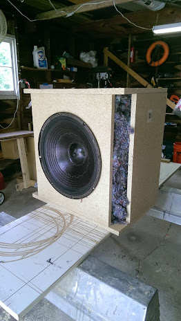
Next is the same cab, but instead of slots on the side I have an 8" woofer on each side with about 3.5" from the woofer frame to the baffle. Each 8" woofer has it's own enclosure within the main cab. The 15 and the 8s were eq'd relatively flat, and the 8s are -8dB, delayed .2ms, and low passed 1st order at 700hz:
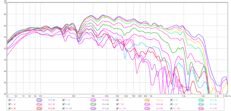
The fr tracks pretty well here too, with maybe a bit less than 100° beamwidth. I'm sure I can narrow the pattern with delay, level, and fr changes to the side drivers. Monopole response below 250hz which I don't like. I don't think that directivity is important below 300hz or so, but an attenuated rear response might help with the front wall notch in the mid-bass.
Last, here's the cab with the side drivers again, only I have about a 15" square opening on the back side of the box as well. Still stuffed with BL and I was hoping to get some rear output cancellation:
The response out to 90° is mostly unchanged but you can see significant rear attenuation.
I measured the monopole (about 1.5cu ft sealed with a Eminence Delta 15" LFA) out to 180° to get a baseline. Very little eq, I think the highs roll off because I didn't have the cab angled towards the mic correctly:
Next is an acoustic resistance box (same box) that has 2 large slots cut on each side of the cab. Total area of the slots is about 150% of the driver sd. The baffle on these is 19" wide. The first slot is about 2" back from the baffle and the cab and slots are stuffed with Bonded Logic:
Fr tracks quite well over most of the range with around 100° beamwidth and good rear attenuation. I'm liking this but ideally I'd like a bit narrower directivity. You can see the pattern widen around 1khz (where I would probably xo) then start beaming soon after due to the driver size. I think the narrowing at 1khz is due to the slot spacing and the baffle width.
Next is the same cab, but instead of slots on the side I have an 8" woofer on each side with about 3.5" from the woofer frame to the baffle. Each 8" woofer has it's own enclosure within the main cab. The 15 and the 8s were eq'd relatively flat, and the 8s are -8dB, delayed .2ms, and low passed 1st order at 700hz:
The fr tracks pretty well here too, with maybe a bit less than 100° beamwidth. I'm sure I can narrow the pattern with delay, level, and fr changes to the side drivers. Monopole response below 250hz which I don't like. I don't think that directivity is important below 300hz or so, but an attenuated rear response might help with the front wall notch in the mid-bass.
Last, here's the cab with the side drivers again, only I have about a 15" square opening on the back side of the box as well. Still stuffed with BL and I was hoping to get some rear output cancellation:
The response out to 90° is mostly unchanged but you can see significant rear attenuation.
puppet - I tried a couple different iterations of the closed box behind the dipole (in my garage, I need to try it outside) and got some pretty goofy results in the 800-1khz range. Goofy being high q peaks and dips beyond 5° or so off axis. Like I said I need to get outside to try that one again.
I also tried a dipole with a sealed woofer above and behind the dipole, thinking that I could get a smoother response but it was still pretty rough.
At this point, despite the title of thread, I'm leaning towards the acoustic resistance box with the slots in the side. I think it's pretty impressive to have a 15 with constant directivity over that kind of bandwidth that's not a dipole. It's a bit wider pattern than I would like but then I don't have to buy more drivers/amps. I'm going to build a test box for my TD15s with a 2" or so roundver and I'll get the side slots up as close to the baffle plane as I can.
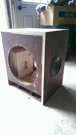
Here's some pics of the different configurations I've been trying.
Side vent with removable back panel:
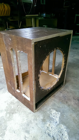
Side 8" drivers with removable back panel:
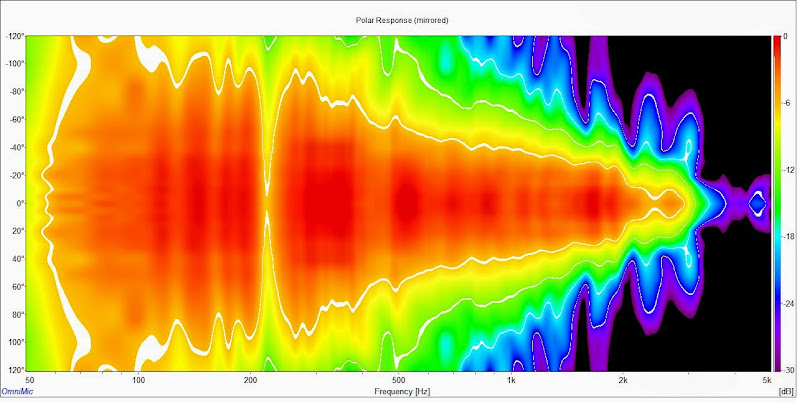
Here are sonograms for the data I've shown so far. I did a bit of post process eq to flatten the response and mimic a usable freq response for easier comparison.
Monopole:
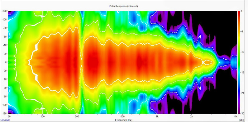
Side Vent:
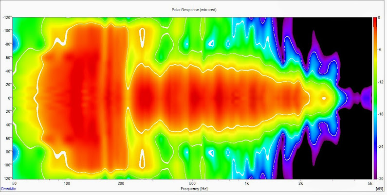
Side 8" divers with a 15" square opening in the back of the cab:
Side vent with removable back panel:
Side 8" drivers with removable back panel:
Here are sonograms for the data I've shown so far. I did a bit of post process eq to flatten the response and mimic a usable freq response for easier comparison.
Monopole:
Side Vent:
Side 8" divers with a 15" square opening in the back of the cab:
Last edited:
I also built a test version of the corner vent model I showed earlier:

If you compare this result with my monopole result from earlier I think it's safe to say that there's little difference in directivity at 500+hz. My thought with the front corner vents was to get them closer to the baffle plane and actually narrow the pattern in this region but it appears that the baffle size dominates. Below 500hz the pattern is a fair bit narrower on my corner vent cab than the monopole. My goal is to maintain a 90ish or better degree pattern from 300 up........so this one didn't work out.
I tried narrowing the baffle, making the vent wider to the back, making it narrower, more stuffing, less stuffing, and I even removed the sides completely. The effect on the direcitivity of these changes was negligible. It only increased or decreased the sensitivity in the 800-1khz region.
At this point my side vent version from post 12 looks the best when comparing the sonograms. It maintains a roughly 100° beamwidth from 300hz and up and it looks like I'll have a bit of room to play in the xo region around 1khz.

My goal here is to use my current midwoofers (TD15m) from 80-1000ish and have controlled directivity from 300hz up. In my room I'd like to have a 60° beamwidth and I'd make elliptical os waveguides to match, but I won't settle for anything more than 90°.
There's really three ways that I see to do this: dipole, cardioid(or variations thereof), or some big horns.
This is very interesting, but I'd like to point out a few things.
First cardioid is even wider than dipole, so that will not get you to the 60 ° that you seek. You can't get to 60° until the drivers radiating area is wide enough to get there independent of the other transducers, i.e. not until the driver itself starts to beam.
Just the other day I tried to do a passive cardioid and did not have much success. The effect was kind of minimal. It was there but nothing dramatic like I was looking for. The electronic, as you have shown, is the way to go - I showed this in my book.
Thanks for posting your work.
If you want to get into the theory; with one driver a monopole is all you can get and 360° is the result. With two drivers you can get the sum of a monopole and a dipole and there will always be two nulls somewhere for a minimum null angle of 180°. With three drivers , you get three nulls 120° apart, etc. etc. You can see that four drivers with specific amplitude shading should just reach the 60° angle that you seek.
Next is the same cab, but instead of slots on the side I have an 8" woofer on each side with about 3.5" from the woofer frame to the baffle. Each 8" woofer has it's own enclosure within the main cab. The 15 and the 8s were eq'd relatively flat, and the 8s are -8dB, delayed .2ms, and low passed 1st order at 700hz ...
At first I though that this would be needed as well, but now I believe that with a DSP unit one would not have to separate the drivers. Just measure each one separately and then EQ each to get the final result that you wanted. Its a linear system so this should work (note should work.)
I think that electronic polar shading will be the future of low frequency enclosure design. Enough of this "T-S QB3" (insert current vogue here) alignment nonsense. It's the pattern that matters NOT the response. One just EQs the response in-situ anyways.
The side vent also has a slot at the bottom which may contribute to its greater pattern control than the diagonal vent setup. The question of whether the DSP version is better or not comes down to 200Hz and below- Dr. Geddes would prefer wide dispersion for maximum modal excitation below Schroeder, and I'm inclined to agree, but the added complexity doesn't seem to be worth the effort given that one can achieve good modal excitation with additional sources in the bass.
The closer damped vent stuffing is entirely possible by removing pieces of the front baffle, though care would be needed to ensure mechanical integrity.
The closer damped vent stuffing is entirely possible by removing pieces of the front baffle, though care would be needed to ensure mechanical integrity.
Thanks for the thoughts guys.
I knew there was no way the passive version would get to 60° but I thought with the right "shading" as you call it that I might get there.
To tell you the truth I'm quite happy with the passive side vent version that pos re-posted above. A nearly 100° pattern from 300-1.1khz is pretty good in my book........without buying more drivers and amps.
I cant figure out how the 4 driver version would work out, is this in your book?
That slot at the bottom in the pic is in fact a poorly made port by whoever built these old cabs. I've blocked it off entirely inside the enclosure so it has no effect.
I was thinking having the vents at the corners of the baffle would have a greater effect but I think that it actually has the opposite effect because there is less of a delay. Hmm
The electronic, as you have shown, is the way to go - I showed this in my book.
Thanks for posting your work.
If you want to get into the theory; with one driver a monopole is all you can get and 360° is the result. With two drivers you can get the sum of a monopole and a dipole and there will always be two nulls somewhere for a minimum null angle of 180°. With three drivers , you get three nulls 120° apart, etc. etc. You can see that four drivers with specific amplitude shading should just reach the 60° angle that you seek.
I knew there was no way the passive version would get to 60° but I thought with the right "shading" as you call it that I might get there.
To tell you the truth I'm quite happy with the passive side vent version that pos re-posted above. A nearly 100° pattern from 300-1.1khz is pretty good in my book........without buying more drivers and amps.
I cant figure out how the 4 driver version would work out, is this in your book?
The side vent also has a slot at the bottom which may contribute to its greater pattern control than the diagonal vent setup.
The closer damped vent stuffing is entirely possible by removing pieces of the front baffle, though care would be needed to ensure mechanical integrity.
That slot at the bottom in the pic is in fact a poorly made port by whoever built these old cabs. I've blocked it off entirely inside the enclosure so it has no effect.
I was thinking having the vents at the corners of the baffle would have a greater effect but I think that it actually has the opposite effect because there is less of a delay. Hmm
The question of whether the DSP version is better or not comes down to 200Hz and below-
I don't think that this is true, in fact theoretically it is definitely not true. Four sources (or two) with DSP simply has more degrees of freedom
This is very likely to be true.the added complexity doesn't seem to be worth the effort given that one can achieve good modal excitation with additional sources in the bass.
In fact I find the whole idea of striving for directivity down to a few hundred Hz kind of a waste of resources. Which is why I don't do it. I can stay below 60° (120° total) down to 500 Hz which narrows to 45° at 1 kHz without doing any of these complicated and inefficient tricks. To me that's a good compromise.
I cant figure out how the 4 driver version would work out, is this in your book?
No, just two drivers are done in the book, but from that study you should be able to easily see how to add two more drivers. I mean you do have to have some level of modeling capability, but it is a straightforward problem.
It used to be that the DSP would be a real limitation, but these days that's not a big deal. The added amps could be an issue, but even those are not too expensive these days, although what one would want - say eight or ten amps in one box- does not seem to be available. With chip amps this doesn't seem like a tough design problem. I just don't do electronics that all.
- Status
- This old topic is closed. If you want to reopen this topic, contact a moderator using the "Report Post" button.
- Home
- Loudspeakers
- Multi-Way
- DSP midrange directivity control aka kinda cardioid