After my successful build of a Synergy horn using BMS 4550, Visaton M10 and Eminence Beta12A-2 for use with my e-drum, I had to have a pair for the living room 😀. The aforementioned horns measured roughly 60x40x50 cm, which is too big for my living room.
Intrigued by the idea of a two-way Synergy horn combined with the sub I already have (a Bill Fitzmaurice Table Tuba based on the now extinct Eminence HL-10C), I set off playing around with a B&C DE250 I had laid my hand on for a very nice price 2nd hand and the Faital Pro 8FE200/8 Ohm that was suggested in the "Suitable midrange cone for bandpass mid in Unity horn"-thread. The Faitals happened to be on sale at TeamAudio.fr for €26.55 each, which was an excellent deal, so I had to hurry up a little .
.
Starting points are:
- covering 100-20000Hz
- crossover at 1 kHz
- not too big
Using Bwaslo's SynCalc v5 excel sheet (thank you VERY much, Bill!) and Hornresp (many thanks David McBean!) I tried various designs. Having done the Synergy calculations before and having learned from various pitfalls doing my first Synergy Horn, the process proceeded a LOT faster this second time 😀. But despite my ferocious halve year studying, reading forums and collecting data BEFORE I even started simulating my first design, I had to go over the material once again to get a grasp of the main design aspects and focus points.
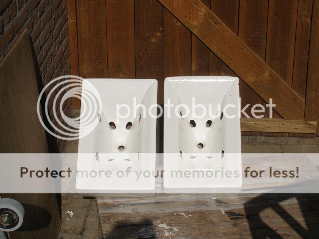
The 8FE200 seemed to simulate quite well right off the bat. I decided on a 90x60 horn. To keep a decent size I had to compromise on the lowest frequency at which horizontal pattern control could be kept. I decided on 500Hz. This resulted in a compact horn: 'Only' 49x32x20 cm. Soon my first proto saw the light. As you can see, I decided to 'cut corners'😀. Makes corner placement much easier 😉.
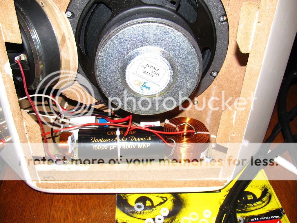
For measurements I used the excellent and free(!) Room Eq Wizard 5 from Hometheatershack (thanks a lot, John Mulcahy!). The yellow graph shows the woofers in an open back configuration (as seen in the picture), so the bottom end is lacking, but the top end is a correct representation of the final (closed) loudspeaker.
The 50 cm2 total mid tap holes seemed a bit much. So I decided to build a second proto with tap holes a quarter the size. Since those big taps showed no huffing signs AT ALL, I figured I could go smaller. And in case the taps were too small, I could always make them bigger quite easily. By the way, I kept to the golden ratio for the tap holes.
This one measured better. The green graph shows a closed speaker, woofers only (tweeter installed, but shorted), no EQ or crossover whatsoever (and not referenced to 2.83 volts).
Now these aren't exactly HiFi-like loudspeaker graphs, but the measurements proved that the woofer was usable from around 100 Hz to 1 kHz. With a little EQ and not too much SPL, even 70 Hz seems doable.
So this looked quite good actually😀.
More progress later. Keep reading 😉
Intrigued by the idea of a two-way Synergy horn combined with the sub I already have (a Bill Fitzmaurice Table Tuba based on the now extinct Eminence HL-10C), I set off playing around with a B&C DE250 I had laid my hand on for a very nice price 2nd hand and the Faital Pro 8FE200/8 Ohm that was suggested in the "Suitable midrange cone for bandpass mid in Unity horn"-thread. The Faitals happened to be on sale at TeamAudio.fr for €26.55 each, which was an excellent deal, so I had to hurry up a little
.Starting points are:
- covering 100-20000Hz
- crossover at 1 kHz
- not too big
Using Bwaslo's SynCalc v5 excel sheet (thank you VERY much, Bill!) and Hornresp (many thanks David McBean!) I tried various designs. Having done the Synergy calculations before and having learned from various pitfalls doing my first Synergy Horn, the process proceeded a LOT faster this second time 😀. But despite my ferocious halve year studying, reading forums and collecting data BEFORE I even started simulating my first design, I had to go over the material once again to get a grasp of the main design aspects and focus points.
The 8FE200 seemed to simulate quite well right off the bat. I decided on a 90x60 horn. To keep a decent size I had to compromise on the lowest frequency at which horizontal pattern control could be kept. I decided on 500Hz. This resulted in a compact horn: 'Only' 49x32x20 cm. Soon my first proto saw the light. As you can see, I decided to 'cut corners'😀. Makes corner placement much easier 😉.
For measurements I used the excellent and free(!) Room Eq Wizard 5 from Hometheatershack (thanks a lot, John Mulcahy!). The yellow graph shows the woofers in an open back configuration (as seen in the picture), so the bottom end is lacking, but the top end is a correct representation of the final (closed) loudspeaker.
The 50 cm2 total mid tap holes seemed a bit much. So I decided to build a second proto with tap holes a quarter the size. Since those big taps showed no huffing signs AT ALL, I figured I could go smaller. And in case the taps were too small, I could always make them bigger quite easily. By the way, I kept to the golden ratio for the tap holes.
This one measured better. The green graph shows a closed speaker, woofers only (tweeter installed, but shorted), no EQ or crossover whatsoever (and not referenced to 2.83 volts).
Now these aren't exactly HiFi-like loudspeaker graphs, but the measurements proved that the woofer was usable from around 100 Hz to 1 kHz. With a little EQ and not too much SPL, even 70 Hz seems doable.
So this looked quite good actually😀.
More progress later. Keep reading 😉
Attachments
-
 SynCalc v5.png33.9 KB · Views: 1,863
 -
 Hornresp 01.png14 KB · Views: 1,859
 -
 Hornresp 02.png12.2 KB · Views: 1,845
 -
 2014-06-29 21.36.48.jpg260.4 KB · Views: 1,868
 -
 2014-06-29 21.38.23.jpg239.4 KB · Views: 1,891
 -
 IMG_1394 small.JPG168.7 KB · Views: 914
 -
 IMG_1399 small.jpg195.3 KB · Views: 749
 -
 IMG_1401 small.JPG176.6 KB · Views: 731
 -
 Proto 2 mids.png53.2 KB · Views: 838
 -
 Proto 1 mids.png47.2 KB · Views: 711
Last edited:
Thanks. I still have to make time for writing another update :s.
I think it will be passive crossover. At the moment it's still active xover. I want to drive it with a 'regular' home theater receiver (yet to be bought), but as far as I've found there are no receivers that allow for an active xover to be inserted between pre and main stage 🙁. I mean, it's not like there's not enough amplifier channels available with today's 11.2 setups...
So it looks like I have to do a passive xover. Unless someone has a suggestion 😀
Cool.
Those look good for a compact PA speaker for use with subwoofers. Definitely going to keep a track of this.
Chris
Those look good for a compact PA speaker for use with subwoofers. Definitely going to keep a track of this.
Chris
Thijs
I see that it usable but needs so much compensation, this is afcourse because the throat chamber of woofers like with me, the sims are not really trustable with the phillips.
But maybe you have not yet seen this.
http://www.diyaudio.com/forums/full...450-ndy-fast-applications-25.html#post4045696
regards
kees
Thijs
I see that it usable but needs so much compensation, this is afcourse because the throat chamber of woofers like with me, the sims are not really trustable with the phillips.
But maybe you have not yet seen this.
http://www.diyaudio.com/forums/full...450-ndy-fast-applications-25.html#post4045696
regards
kees
There is more here:
http://www.diyaudio.com/forums/full-range/261427-40-full-range-synergy.html
and the end result is..?
Hi Thijs,
This morning I was going through some diyAudio threads and came across your Synergy experiments. Must say, I'm impressed, more than that even considering the knowledge you had when starting, ending this far.
I also had (one of the many) idea's on going for a synergy, using the 8FE200. They simm quite good, are affordable and take a serious beating (I use 4 of them for a bass guitar cabinet and was impressed by the result).
QUESTION:
Did you end this version and is there some update / latest development info you would like to share.
One thought I have is, make it go down to 180 Hz or so (bigger Horn but still not to big). 180 because that is a nice freq. to cross-over at considering using it for Live / band / P.A. purposes. All details on vocals, guitar and keyboard, copper, etc. start around that area. Resulting in one point source device (horn) handling all information that is most important and where our ears are most effective. Combine this with e.g. a THAM15 (or THAM12) or any other Tapped Horn and you have a compact, loud and very audible P.A at hand. DSP, 2 digital amps finish the picture. Fits right in a passenger car for a change, easy to install.
Looking forward to hear from you.
kind regards,
Re' cutting the corners
My first corner horn prototype used the 8FE200 so let me share some of my experience. I think Onni also used the 8FE200 in his Synergy. Mine was designed to fit tightly into corners. As a result, like yours, there was not much room behind the 8Fe200's magnet. It was almost up tight against the side/back wall of the cabinet.
I initially fooled myself into thinking the driver was working smoothly past 1 Khz by running the box without the cover off and piling up absorption behind the driver to absorb the back wave. I needed a volume plug taking up space under the woofer cone to get it up that high. I guess your frequency responses are unsmoothed? With some smoothing or gating they should clean up.
I was terribly disappointed when I put the covers on the box to see a notch just below 1 Khz that I just couldn't get rid of. I eventually I concluded it was cancellation from a reflection off the side/back covers meeting with the direct radiation at the holes through the horn walls. I see the same kind of notch in your frequency response but then you said your measurements were with open backs.
I think the 8FE200 will work fine if you provide enough room behind it for stuffing to absorb the back wave. In thread "My Synergy Corner Horns and Bass Bins" I didn't want to change the box so I switched from a single 8FE200 on each side to a pair of 4FE35's, which covered down to 200 Hz where the bass bins took over. But I want to do another, non-corner version of the box using the 8fe200 for use as a center channel so I look forward to seeing how yours turn out.
Good luck
It's been long overdue that I posted an update... So here we go.Did you end this version and is there some update / latest development info you would like to share.
These are now my main left/right speakers in my living room. They are driven by a Denon AVR-4310. I did use its Audyssey room measurement system, but I like the sound better if it's deactivated. It sounds a little dull and processed when Audyssey is enabled.
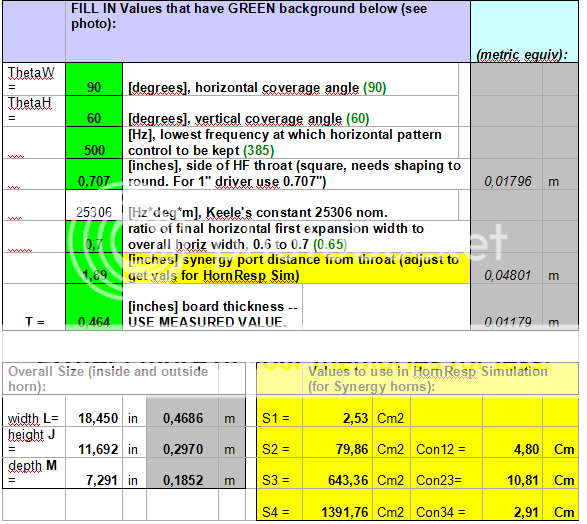
Here's the SynCalc sheet (thank you Bill Waslo!):
An externally hosted image should be here but it was not working when we last tested it.
You can find some documentation I used here: https://drive.google.com/open?id=0B85db-5ynA7wV0diWXZiQklSd0U.
They are bass reflex with two ports (not 4 like in the pics below; I tried modelling the vented chamber using WinISD, but that wasn't a success, had to close two up again; It was basically trial and error). The ports are made with standard 32mm diameter 45 degree PVC piping pieces. Angled, because otherwise they wouldn't fit.
An externally hosted image should be here but it was not working when we last tested it.
An externally hosted image should be here but it was not working when we last tested it.
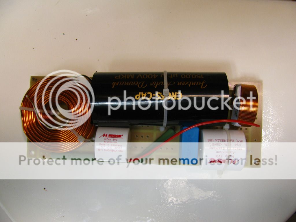
I ended up doing a passive crossover:
An externally hosted image should be here but it was not working when we last tested it.
An externally hosted image should be here but it was not working when we last tested it.
An externally hosted image should be here but it was not working when we last tested it.
I think 180 Hz is far too high for a sub. For the record, these 2-way Synergies easily go down to 100 Hz. In my living room they have a large bump at 60 Hz... And from my short 'loudness' tests the bottleneck is the compression driver, not the two 8FE200's, when HP'ed @100 Hz. 120 dB@1m is certainly doable.One thought I have is, make it go down to 180 Hz or so (bigger Horn but still not to big). 180 because that is a nice freq. to cross-over at considering using it for Live / band / P.A. purposes.
They sound fine and have the same kind of sound usually found in Synergy horns. Good imaging and a sound 'image' that is floating in front of you. But to be honest, my 3-way Synergies sound better. I suspect the BMS4550 driver to be more 'hifi'-ish, or maybe it's the additional mids that couple better in the horn... But my girlfriend once said that she had been spoiled by them, because when she hears music somewhere else almost all of the times she thinks it sounds worse than at home 😀.
I almost forgot to mention: my living room sub is a Bill Fitzmaurice Table Tuba, but when casually listening music it's not really missed if it is switched off. You're still listening to four 8" woofers after all...
The images from google drive didn't work, so here's a retry using photobucket...
It's been long overdue that I posted an update... So here we go.
These are now my main left/right speakers in my living room. They are driven by a Denon AVR-4310. I did use its Audyssey room measurement system, but I like the sound better when it's deactivated. It sounds a little dull and processed when Audyssey is enabled.
Here's the SynCalc sheet (thank you Bill Waslo!):
You can find some documentation I used here: https://drive.google.com/open?id=0B85db-5ynA7wV0diWXZiQklSd0U.
They are bass reflex with two ports (not 4 like in the pics below; I tried modelling the vented chamber using WinISD, but that wasn't a success, had to close two up again; It was basically trial and error). The ports are made with standard 32mm diameter 45 degree PVC piping pieces. Angled, because otherwise they wouldn't fit.

I ended up doing a passive crossover:
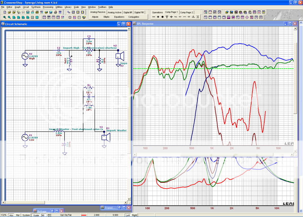
Graph right top:
Bright blue, bright red are curves without filter,
Dark blue/red are curves with filter,
Green is summed/final curve.
Bottom graph: impedance plots, bright red is total curve, just touching 3.5 Ohms @ 200 Hz.
I think 180 Hz is far too high for a sub. For the record, these 2-way Synergies easily go down to 100 Hz. In my living room they have a large bump at 60 Hz... And from my short 'loudness' tests the bottleneck is the compression driver, not the two 8FE200's, when HP'ed @100 Hz. 120 dB@1m is certainly doable.
They sound fine and have the same kind of sound usually found in Synergy horns. Good imaging and a sound 'image' that is floating in front of you. But to be honest, my 3-way Synergies sound better. I suspect the BMS4550 driver to be more 'hifi'-ish, or maybe it's the additional mids that couple better in the horn... But my girlfriend once said that she had been spoiled by them, because when she hears music somewhere else almost all of the times she thinks it sounds worse than at home 😀.
I almost forgot to mention: my living room sub is a Bill Fitzmaurice Table Tuba, but when casually listening music it's not really missed if it is switched off. You're still listening to four 8" woofers after all...
Gorgeous looking horns there, Thijs666.
Not surprised the ports didn't work, there isn't much volume behind those woofers at all. But if you want to make them play lower with the boxes sealed, a Linkwitz Transform EQ on the bass might get you there. I'm using two 6FE100s with a sealed box, LT applied to pull them down to 50Hz, and it works surprisingly well for music.
Not surprised the ports didn't work, there isn't much volume behind those woofers at all. But if you want to make them play lower with the boxes sealed, a Linkwitz Transform EQ on the bass might get you there. I'm using two 6FE100s with a sealed box, LT applied to pull them down to 50Hz, and it works surprisingly well for music.
Gorgeous looking horns there, Thijs666.
Not surprised the ports didn't work, there isn't much volume behind those woofers at all. But if you want to make them play lower with the boxes sealed, a Linkwitz Transform EQ on the bass might get you there. I'm using two 6FE100s with a sealed box, LT applied to pull them down to 50Hz, and it works surprisingly well for music.
+1 beautifully made enclosures. Nice finish and I like the shape.

What is the rear chamber volume? Bushemeister got surprisingly deep bass extension with a pair of 8in SB Acoustics woofers on the sealed rear chamber xBush horn. 40Hz as I recall.
Although, there is something about them that reminds me of a porcelain wash sink? 🙂
Last edited:
Thank you!Gorgeous looking horns there, Thijs666.
Not surprised the ports didn't work, there isn't much volume behind those woofers at all. But if you want to make them play lower with the boxes sealed, a Linkwitz Transform EQ on the bass might get you there. I'm using two 6FE100s with a sealed box, LT applied to pull them down to 50Hz, and it works surprisingly well for music.
Well, actually the prots worked quite ok, but the tuning was way too low with four. That’s why I reduced them to two. Now they augment the 80-or so-Hz region, which was what I was aiming for. But in my living room they go low enough to use them without a sub. Of course it sound better with the sub...
Thanks again 😱. To be honest, the finish is just regular high gloss white paint 😀. Nothing special. They are quite shiny in direct sunlight, I agree.+1 beautifully made enclosures. Nice finish and I like the shape.
What is the rear chamber volume? Bushemeister got surprisingly deep bass extension with a pair of 8in SB Acoustics woofers on the sealed rear chamber xBush horn. 40Hz as I recall.
Although, there is something about them that reminds me of a porcelain wash sink? 🙂
Chamber volume? I have no idea (anymore). I think I did an in-the-ballpark-calculation, threw that into WinISD, concluded after measuring that it didn't work, taped some ports shut until I liked the graph and closed the ports I didn't need. I also experimented with port length. Turned out two standard 45 degree angled pieces of PVC were al that I needed.
For Synergies they are quite small, but making them white also adds to the waf 😀.
Last edited:
Thanks for sharing your findings with us.
I am in the process of designing my own horn, but cannot make the numbers everybody use fit.
A) : Perhaps you can explain why S1 is almost universal 2,53 cm2 in various simulations ?
I mean: The horn sides in Bills spreadsheet all aim to a 0,7" square throat, equivalent to 3,16 cm2.
This throat is later reamed by everybody to 1" dia, to fit the compression driver, equivalent to 5,06 cm2.
If you simulate a horn with S1 5,06 cm2 (everything else equal) you get a LOT different data.
To me, everybody are simulating one horn, then they build another.
Why 2,53 cm2 ??
B) : In one of your google-cloud documents you calculate areas, circumferences and half wavelenghts for 900, 1000 and 1200 Hz crossover frequencies, being 14,3 / 17,2 / 19 cm respectively.
So far so good. Tom Danley specifically states "half wavelength" in the patents.
Your final line then reverse the calculation, by grabbing S2 from Bills Syncalc (..allright), obtaining 1083 Hz crossover frequency (..allright), and then concluding a half wavelength (or S2 tap) of 4,8 cm ! (...NOT allright).
This is close to 1/8 wavelength !
I would be obliged if you could explain the vast discrepancies in A) and B) above to us.
I'll take a stab at it.
S1 in the spreadsheet is what it is because that is how the horn is built. The S1 value falls out of the geometry/trigonometry calculations for the sides and mouth. But, as you say, its later drilled out to 5.06 cm2 and so that is what you should simulate with.
But the horn extends back into the compression driver a distance that depends on the CD's construction. So before simulating you should increase the L12 by this distance. You can find acoustic path lengths for various compression drivers by googling. I use 6.3 cm for the BMS4550, which is about 2x the norm. If you don't take this into account, you may end up with less mid BW than you expected.
The distance that matters in B) is the distance from the centroid of the mid ports, or rather its projection onto the axis of the horn, to the surface within the CD from which sound reflects and returns to the mid port to cause a null. This distance must be less than 1/4 wavelength at the XO frequency; else the null will be within the mid's passband. To be clear: the one way distance must be less than 1/4 wavelength so the reflection round trip distance is less than 1/2 wavelength. It is not just the L12 but the L12 plus the acoustic path length within the CD that comprises the one-way path length.
Don't forget that the horn circumference at S2 should be less than a wavelength at the XO frequency and that the distance between mid ports should be less than 1/4 wavelength at XO. This rule may drive you to a lower XO than determined by the reflection null frequency.
Thanks for stabbing nc535 🙂
Reg. A (S1):
Well, I disagree here, I'm afraid. Its not how its built, since everybody reams it to 5.06 cm2, but perhaps how its designed.
Trouble is: If you simulate/design with 5.06 cm2 throat you get A LOT different Hornresp data than Bill shows, and later documents by measurement.
So, something is still rotten....
Reg. B (L12):
It makes sense what you write.
My problem is that Bill doesnt give much comment to this crucial distance.
My guess is that the DE250 and Bills Celestion drivers have about the same acoustic distance from "back inside" to the throat.
Has anyone actually tried Tom Danleys method from the patent :
Wire the HI and MID driver out-of-phase; make a sweep; and thus determined the exact acoustic cross-over frequency by the null-output ?
(and then, also by Toms advice, combined it with a crossover-circuit having a 180° phase shift at that frequency. 2nd order Butterworth, I believe)
I mis-spoke slightly. I meant the .707" square throat and the geometry on top of that is how its built. 2.53 for S1 doesn't make sense to me either but if you look at the formulas you'll see that the value for S1 is orthogonal to the rest of the geometry; its a side calculation based on the value entered into the 4th green box down, the value for the side of the square throat that needs shaping to round.
When you drill out the throat with a 1" drill you get 5 sq cm at S1 and that is what you should simulate with. The expansion from there to S2 isn't perfectly CON or EXP. Part of the process is shaping the throat and completing the round to square and/or rectangular conversion with infill in the corners. Yes, all that does make a difference, some of which shows up in the simulation. Don't expect too much from the simulation. Get the mid holes in a workable location and right sized and do the rest in the XO.
When you drill out the throat with a 1" drill you get 5 sq cm at S1 and that is what you should simulate with. The expansion from there to S2 isn't perfectly CON or EXP. Part of the process is shaping the throat and completing the round to square and/or rectangular conversion with infill in the corners. Yes, all that does make a difference, some of which shows up in the simulation. Don't expect too much from the simulation. Get the mid holes in a workable location and right sized and do the rest in the XO.
Thanks for stabbing nc535 🙂
Reg. A (S1):
Well, I disagree here, I'm afraid. Its not how its built, since everybody reams it to 5.06 cm2, but perhaps how its designed.
Trouble is: If you simulate/design with 5.06 cm2 throat you get A LOT different Hornresp data than Bill shows, and later documents by measurement.
So, something is still rotten....
Bill's spreadsheet will give you the dimensions and angles to cut all the panels for a horn, if you use 2.53cm2 the dimensions for the horn will allow you to build a horn with a 0.7" throat that can be drilled out to 1". That is why it is based on that value.
If you only use the spreadsheet to get Hornresp inputs then as you say you will need to change it to make an accurate simulation.
Reg. B (L12):
It makes sense what you write.
My problem is that Bill doesnt give much comment to this crucial distance.
My guess is that the DE250 and Bills Celestion drivers have about the same acoustic distance from "back inside" to the throat.
nc535 is right and you very much need to account for the path length of the CD, and the DE250 and Celestion CD's have a much smaller path length around 35mm.
There is some good information here in the posts from hulkss about hornresp simulation from post #854 onwards
http://www.diyaudio.com/forums/multi-way/88237-suitable-midrange-cone-bandpass-mid-unity-horn-86.html
Also if you use the multiple entry horn model some of these things can be done differently but bill's document was written before that was available.
- Status
- Not open for further replies.
- Home
- Loudspeakers
- Multi-Way
- Synergy with DE250 an 8FE200