Here are two white papers done by Jeff Bagby for measurements. One is to find the actual Z-offset of the drivers, which is needed for accurate crossover modeling. The other is how to get quasi-anechoic measurements of an individual driver.
Use this first to get the acoustic offsets. Don't move the mic. Whatever measuerment distance you use needs to be put into PCD as the design distance. However, your current build according to the picture has different offsets between your midrange drivers. They really need to be in line in the z-axis. This technique won't work if they are not. It will also cause all sorts of comb filtering and cancellations. The TMMWW layout will also cause this. That is why people are sugesting going with a MTMWW or WMTMW layout.
View attachment Finding the Relative Acoustic Offset in PCD (1).pdf
Now go back and measure the woofers and midranges using this technique. You only need to measure one of each, as it will give you the approximate anechoic response. Then use the response for both files you upload and make sure the different x, y, and z axis all display the real life offsets.
View attachment White Paper - Accurate In-Room Frequency Response to 10Hz.pdf
No, you are right, top mid to bottom woofer might get pretty far, but better to get the midrange right I think. Better yet would be a WMTMW. If you can, I would try to go with the 2 woofers - can you not incorporate the MTM box within the larger woofer box? That should give you some more volume to work with than the way you have things assembled right now. And/or maybe increase the depth?
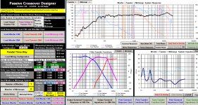
Yes, input all drivers separately into PCD. It can even simulate more than 2 drivers but you need to do it in 2 steps, inputting 2 drivers at a time and combining them and then inputting them as two pairs afterwards (not that that is what you need to do in your case).
Yes, input all drivers separately into PCD. It can even simulate more than 2 drivers but you need to do it in 2 steps, inputting 2 drivers at a time and combining them and then inputting them as two pairs afterwards (not that that is what you need to do in your case).
One thing I would question is the zoffsets. If using jreave's number 1 technique (how I have done my measurements) I do not believe that you should put in any z offsets. As the mic has not moved, the *total* offset, both y and z should be incorporated into the measurements.
With the concerns about Woofer to mid distances, it is no where near as much as a problem as mid to tweeter distance, because the frequency is lower. If you crossover at say 300Hz then the wavelength at this frequency is approx 114cm. Not a major issue")
Thanks for the links armeker, I'll have to check that out. I've been wanting to learn how to do that for some time!
Tony.
With the concerns about Woofer to mid distances, it is no where near as much as a problem as mid to tweeter distance, because the frequency is lower. If you crossover at say 300Hz then the wavelength at this frequency is approx 114cm. Not a major issue
Thanks for the links armeker, I'll have to check that out. I've been wanting to learn how to do that for some time!
Tony.
I'm going to have to try the z-offset calculation in Jeffs pdf linked above... that seems to indicate the entry of the z-offsets *IS* necessary.
I'm wondering if this is more of a PCD calibration?? I use a similar technique when doing my sims (but I use speaker workshop for the final tweaking of the crossover)
I measure the drivers individually, and then with the realized crossover. All from the same point. I then compare the measured response to the crossover simulation from the individual drivers... It is never quite as accurate a match as Jeff's example (though still very close) so maybe I do need to work out this z-offset afterall. I'll be interested to see how the drivers sum in SW when measured as per Jeff's instructions.
Tony.
OK So I did some measurements today. I haven't looked at PCD yet but I just imported them into speaker workshop.
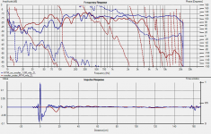
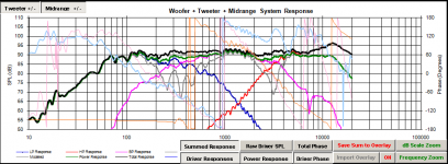
Below is comparison of actual measurement (as per jeffs instructions) of both my 10" woofer and my MTM's running together which is the blue trace. The black trace is speaker workshop sim with a network set up containing just the drivers with the measurements done as per Jeff's PDF.
I have not put in any offsets (Z or otherwise, speaker workshop only allows for Z offset).
I would say that the correlation is pretty good. I doubt that any z offset is going to make these closer. So It seems to me that the process used for PCD is more for PCD's inner workings, and not because the measurements don't have the relative offset already in them.
2nd pic shows the individual measurements as used in the sim. You can clearly see that there is quite a difference in the offset of woofer compared to the MTM. around 25cm! This is both Z offset and path length difference.
C2C distance between the woofer and the MTM's tweeter is about 78cm...
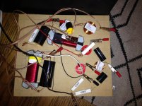
third pic shows my work in progress analog active crossover crossing these two at 250Hz 4th order bessel accoustic target. The filters for this were simmed in speaker workshop using in room 1 octave smoothed measurements.
Tony.
Below is comparison of actual measurement (as per jeffs instructions) of both my 10" woofer and my MTM's running together which is the blue trace. The black trace is speaker workshop sim with a network set up containing just the drivers with the measurements done as per Jeff's PDF.
I have not put in any offsets (Z or otherwise, speaker workshop only allows for Z offset).
I would say that the correlation is pretty good. I doubt that any z offset is going to make these closer. So It seems to me that the process used for PCD is more for PCD's inner workings, and not because the measurements don't have the relative offset already in them.
2nd pic shows the individual measurements as used in the sim. You can clearly see that there is quite a difference in the offset of woofer compared to the MTM. around 25cm! This is both Z offset and path length difference.
C2C distance between the woofer and the MTM's tweeter is about 78cm...
third pic shows my work in progress analog active crossover crossing these two at 250Hz 4th order bessel accoustic target. The filters for this were simmed in speaker workshop using in room 1 octave smoothed measurements.
Tony.
Attachments
OK so inputting the measurements above into PCD (after scaling and removing the comments that holm impusle puts in) I find that with no offset data entered into PCD it sums pretty much exactly the same as speakerworkshop does.
So I stand by what I said before. *IF* your measurements have been all taken from the same point without moving anything, and time zero locked, then if you put no offsets into PCD it should simulate correctly.
Now if you want to use the features of pcd to do off axis simulations then you probably need to put in the offset information.
I'm not really sure what Jeff's Relative acoustic offset is. Perhaps it is something that you need to do if you don't have a facility like Zero locking in holm impulse (eg both of your measurements have the impulse at time zero, rather than at their actual offset positions).
Tony.
Attachments
OK I reset my woofer measurement to have time zero at the impulse peak, re-exported and imported into PCD.
Now I need to put in driver offset's and Z offset to get back to matching data So Jeff's procedure posted above is necessary if you have measurements that do not have the acoustic offset already built in If you use holm impulse and the zero lock feature The acoustic offset IS built in to the measurements, which explains why I have not needed to do this in the past.
I'm happy to get to the bottom of that, hopefully it is useful for someone else as well.
Tony.
Now I need to put in driver offset's and Z offset to get back to matching data
So Jeff's procedure posted above is necessary if you have measurements that do not have the acoustic offset already built in If you use holm impulse and the zero lock feature The acoustic offset IS built in to the measurements, which explains why I have not needed to do this in the past. I'm happy to get to the bottom of that, hopefully it is useful for someone else as well.
Tony.
Attachments
Without really knowing it I went through the same process as wintermute. The phrasing of the T=0 setting in REW is weird, and I prefer to use REW as there is NO manipulation of text before importing into PCD or response modeler:
I did NOT have the "T=0 set to impulse peak" option selected and without moving the mic, I measured individual drivers and then all together. The overlay and PCD-predicted sum have about the same amount of variation as wintermute's last post (3-4dB in places) with NO offsets entered. So I guess that means REW can time lock? Is this as good as I'm gonna get?! What are we doing differently than Jeff that we don't enter any offset info and get similar-ish results?
Unless I'm not thinking of something, with 3-4dB of variation I could design the perfect crossover but when my components arrive and I hook them up I'm not sure what I'm gonna get. I suppose the best option then is to make the new measurement (with crossover in place) the overlay, and manipulate the PCD sum to match that, then adjust XO settings to correct issues. Otherwise you're guessing on changes, then you have to wait 3 days for new XO parts everytime you make a change?!
Why don't we load the ZMA when trying to match up with the overlay? Since it's MTM, do I select 2 mids wired in series? It takes me further from the overlay when I do that. Is all of this stuff just common knowledge and I am behind? How are so many people designing their own 3-way speakers successfully? Ugh
Screen Shot 2014-07-30 at 11.39.58 AM.png
Attachments
Last edited:
for the real crossover sim (vs the procedure outlined by jeff for getting relative acoustic offset) you definetly do need to have your actual impedance data!
Jeffs procedure is measurements of the raw drivers, individually, and playing together (with no crossover) so the impedance is irrelevant in that case. The impedance is important because it affects how the filters perform.
rew's impedance measurement is very good. Ideally measure the impedance at the same spot you do the accoustic measurements.
For my MTM I did the measurement for the M's with both running, and used it as a single driver in REW (not two) with NO offsets. This worked well.
Tony.
I used response modeler to create the ZMA files as I haven't figured out how to measure impedance without buying DATS. As in physically how do I do it? I entered all the T/S parameters and vent tunings, etc so I'm just hoping that it's fairly accurate.
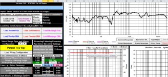
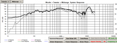
I entered the mids into PCD separately with 0 offset but didn't appear to have any negative effect.
Here is the PCD sim with the mid polarity in both positions. It's not the ideal trace, but I have low expectations for it actually turning out like that anyway. . .
Screen Shot 2014-07-30 at 6.08.43 PM.png
Screen Shot 2014-07-30 at 6.08.27 PM.png
This is with measurements that are taken pretty far from any boundaries so I'm concerned about dealing with too much 100-200Hz when I put it against the wall.
Attachments
impedance measurements are actually very easy. All you need is a simple cable or jig. The simplist can be made for a few dollars. Cables
Just make up the impedance cable above and use the impedance measurement function of rew. if you get weird results reverse the channels
You are getting good nulls in the sim, but I would trust it more with actual impedance measurements.
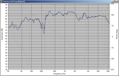
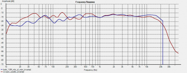
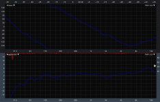
Not sure how the bass is going to go. As a very rough comparison, here are measurements I made of my "three way" in room, compared to outside. 1/3 octave smoothed to make it a little easier to see the trends. The speakers are normally (in room) about 40cm from the wall, and at about a 30 deg angle to it. not butt up against it.
red trace is in room. blue trace is outside. you can see there is quite a bit of room gain. This iteration of the active crossover was done using in room measurements at the listening position (1 octave smoothed before modeling).
I'm not sure it is a good approach, but certainly it seems to have resulted in a "mostly" more flat in room response... there is a bit of an issue between about 150 and 400 Hz... crossover frequency is 250Hz. Phase matching is not great when implemented (was ok in the sim) so I think my 1 octave smoothing was going a bit far
Tony.
Just make up the impedance cable above and use the impedance measurement function of rew. if you get weird results reverse the channels
You are getting good nulls in the sim, but I would trust it more with actual impedance measurements.
Not sure how the bass is going to go. As a very rough comparison, here are measurements I made of my "three way" in room, compared to outside. 1/3 octave smoothed to make it a little easier to see the trends. The speakers are normally (in room) about 40cm from the wall, and at about a 30 deg angle to it. not butt up against it.
red trace is in room. blue trace is outside. you can see there is quite a bit of room gain. This iteration of the active crossover was done using in room measurements at the listening position (1 octave smoothed before modeling).
I'm not sure it is a good approach, but certainly it seems to have resulted in a "mostly" more flat in room response... there is a bit of an issue between about 150 and 400 Hz... crossover frequency is 250Hz. Phase matching is not great when implemented (was ok in the sim) so I think my 1 octave smoothing was going a bit far
Tony.
Attachments
Last edited:
Tony, thanks for the link! I've found so many other WAY more complicated ways to measure impedance.
Thanks for sharing that picture. I was really wanting that data from someone else to compare. I really like the extended response, but mine may be a bit more extreme as it's ending up on a brick hearth in front of a brick fireplace. Which is why I initially took all my measurements in front of a brick wall, so I wouldn't have to guess about the effects. But alas, it lead to unreliable data (I think).
I just posted this in another thread, but here is a dropbox folder with all my FRD and ZMA files as well as screen shots of PCD7 for any and all to look at and comment on.
https://www.dropbox.com/l/loAfpDw2RRcPB3dJi6lZIu
Crash
Last edited:
Long term solution
Hi G Speakers / Crash,
Just saw this thread and a bit about you being "on time over budget" or something...If you are designing commercially you might want to take a look at ..... http://www.rationalacoustics.com
In my experience the best way to improve the quality of my products and service was to invest in Smaart software and their fantastic tutorial courses.....
Not only does their software leave everything else looking rather over priced or ineffective (or both!) but you get to mix with top industry professionals from Pro Sound and loudspeaker design. These guys have a vast pool of expert knowledge and will teach you everything you need to know....
In just a few months you will have a completely new understanding of the speaker / room performance which in itself is fantastic!
In addition....A whole new world of previously unimaginable design options (esp how to utilise DSP & active power amplification) will open up.....
You will be free of the 100 year old straight jacket of "passive crossovers and drivers in a box"
I know that all sounds a bit to radical but Smaart really is off the grid amazing!
Good luck which ever way you go and hope the above helps.
Cheers
Derek.
Hey Derek! Thanks for taking time to reply! You gave some great advice and I completely agree. The reason this stuff is tricky for me is because I come from that world. I have been using Smaart for years and understand FIR filters and DSP much better than passive crossovers. I think this is opposite of how most people do it so it's been difficult to rearrange what has been engrained in me over years of live sound. And yes rational acoustics has some GREAT resources that it's probably time to revisit. Cheers!
Crash
Crash
Great minds....!!
Hey Crash,
You are welcome and I am delighted you are already Smaart aware!
Here is an idea....Contact the guys at B&O and open an OEM account ( PM me if you want as I can help you here) and then OEM some mini DSP crossovers / Eq modules....You are done!
You will then be able to rapidly and consistantly produce ultra compact & efficient active monitors for studio / home cinema / stereo use and tune them for near-field / far-field, in-wall or floor standing locations and difficult room acoustics.
The cost / performance will simply blow away any passive crossover / single big amp possibilities...
Having recently bought some of the new ICE power modules with integrated power supplies and compared them to good class AB as well as Hypex N Core I have concluded that you need to spend 5 or 6 times more than the cost of the ICE power to get any noticeable improvement....The ICE power are very, very good!
There are lots of great DSP options but an OEM with Mini DSP is a great starting point and they are good guys to deal with.
All the best
Derek.

Final responses
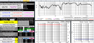
Ok everybody, sorry it took so long, but here is what I ended up with. I think I only changed out 2 caps by a small amount.
Here is the original design and testing of design:
IMG_5021.jpg
Screen Shot 2014-07-31 at 7.29.29 PM.png
After testing and finalizing:
photo 1.jpg
photo 2.jpg
Here is what I landed on:
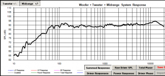
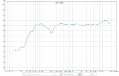
Outside, on axis:
Screen Shot 2014-09-02 at 3.57.52 PM.png
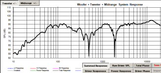
Inside on Axis:
tw1 3.3 inside on-axis final.png
Inside average of 0-45 degrees:
tw1 3.3 inside 0-45 avg final.png
Cabinet construction:
photo 3.jpg
I decided to keep the 14k bump as it almost exactly matches his current center channel, and I'll change it with an EQ if I don't like all 3 together. When I flip mid polarity the LF/mid null is fantastic, even better that predicted. The mid/HF null is a disappointing 6-8 dB, but I don't entirely trust that measurement for various reasons. Regardless, I am quite happy with the end result. The overall tone is fantastic, not as sensitive as my MTM but tons of horsepower if you have the amp for it. I was never very convinced about the Usher 9950-20 for the tweeter. It has incredible reviews, but I can't seem to "un-hear" some harmonics that play in both of them. It doesn't show up as much when I measure harmonic distortion, but something is there that I am sensitive to. But the lay person would never hear it.
I still have to cut a piece of perforated stainless steel to mount in front of the speakers, but the only effect it had on measurements was some minor comb filtering on that 14k hump.
Thank you all for your help, sincerely. If it wasn't for these threads I would probably just be handing him his money back in defeat at this point! Hope to be back here with my next project!
Ok everybody, sorry it took so long, but here is what I ended up with. I think I only changed out 2 caps by a small amount.
Here is the original design and testing of design:
IMG_5021.jpg
Screen Shot 2014-07-31 at 7.29.29 PM.png
After testing and finalizing:
photo 1.jpg
photo 2.jpg
Here is what I landed on:
Outside, on axis:
Screen Shot 2014-09-02 at 3.57.52 PM.png
Inside on Axis:
tw1 3.3 inside on-axis final.png
Inside average of 0-45 degrees:
tw1 3.3 inside 0-45 avg final.png
Cabinet construction:
photo 3.jpg
I decided to keep the 14k bump as it almost exactly matches his current center channel, and I'll change it with an EQ if I don't like all 3 together. When I flip mid polarity the LF/mid null is fantastic, even better that predicted. The mid/HF null is a disappointing 6-8 dB, but I don't entirely trust that measurement for various reasons. Regardless, I am quite happy with the end result. The overall tone is fantastic, not as sensitive as my MTM but tons of horsepower if you have the amp for it. I was never very convinced about the Usher 9950-20 for the tweeter. It has incredible reviews, but I can't seem to "un-hear" some harmonics that play in both of them. It doesn't show up as much when I measure harmonic distortion, but something is there that I am sensitive to. But the lay person would never hear it.
I still have to cut a piece of perforated stainless steel to mount in front of the speakers, but the only effect it had on measurements was some minor comb filtering on that 14k hump.
Thank you all for your help, sincerely. If it wasn't for these threads I would probably just be handing him his money back in defeat at this point! Hope to be back here with my next project!
Attachments
-
 Screen Shot 2014-07-31 at 7.29.29 PM.png89.1 KB · Views: 29
 -
 IMG_5021.jpg816.6 KB · Views: 24
 -
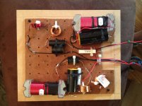 photo 1.jpg956.2 KB · Views: 23
 -
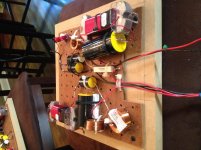 photo 2.jpg849.5 KB · Views: 20
 -
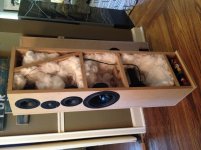 photo 3.jpg914.8 KB · Views: 30
 -
 Screen Shot 2014-09-02 at 3.57.52 PM.png65.9 KB · Views: 34
 -
 tw1 3.3 inside on-axis final.png32 KB · Views: 22
 -
 tw1 3.3 inside 0-45 avg final.png34.3 KB · Views: 21
Last edited:
- Status
- This old topic is closed. If you want to reopen this topic, contact a moderator using the "Report Post" button.
- Home
- Loudspeakers
- Multi-Way
- Tricky 5-driver 3-way design issues, help?